
When page is bookmarked text here is referenced verbatim

The locked anti-phase motor controller circuit is an essential component for applications requiring precise motor control, particularly in robotics. The use of general-purpose transistors allows for a cost-effective solution while maintaining the necessary functionality. The H-Bridge configuration is critical, as it enables bidirectional control of the motor. In this setup, the transistors are strategically activated to ensure that only one pair of transistors conducts at a time, preventing the invalid condition that could lead to damage.
When implementing this circuit, attention must be paid to the PWM frequency and duty cycle to achieve the desired motor speed and direction. The choice of transistors should be made carefully, considering their current ratings and switching capabilities to ensure reliable operation. Additionally, the use of an inverter in the design enhances safety by preventing simultaneous conduction of all transistors, thereby protecting the circuit from potential failures.
The tutorial serves as a practical guide for building the motor controller on a breadboard, with clear instructions and visual aids to facilitate the assembly process. It is important to follow the schematic closely and verify connections to ensure proper functionality. The enhancements made to the circuit design aim to improve performance and reliability, making it suitable for various robotics applications. Overall, this locked anti-phase motor controller represents a valuable tool for hobbyists and engineers working with small DC motors in robotic systems.The photo depicts a completed (bread-barded) locked anti-phase motor controller using general purpose transistors, which allows you to control small DC motors for robotics applications. The big picture problem is that a normal DC motor controller does not have the "braking" function, which allows for precise control.
Solving this partially or comp letely is important because precise motor control is needed in robotics applications, and where cost is a factor. A DC motor is fairly cheap, dependent on size, compared to other types of motors. This tutorial shows you how to bread-board the motor controller hardware, and program the Netburner to output the lcked anti-phase PWM.
It takes approximately 3 hours to complete. This tutorial`s motivation is to use the Embedded Netburner MOD5213 to control a DC motor for small robotics applications. Readers of this tutorial assumes the reader has the following background and interests: *If your computer does not have a 9 pin RS-232 Serial port, you will need to purchase a USB Adapter.
They can be found almost anywhere on the internet, or in a computer store near you. Before we actually begin the motor controller, there are a few things that need to be addressed first. What is an H-Bridge, and what does it do (and) What is a locked anti-phase motor driver, and how does it work First of all, an H-bridge is a basic motor controller in which 4 transistors are configured with a motor to allow full forward and reverse of the motor, rather than just one direction.
As you can see in the figure below, how the motor controller gets its name. In order to drive the motor forward, transistors Q1 and Q3 must be driven (while Q2 and 4 are OFF). To drive the motor in reverse, Q2 and 4 should be driven, while Q1 and Q3 should remain off. This allows for the full reversal of power through the motor. NOTE! There is an invalid condition where all the transistors are driven, and in that case, the motor is bypassed, and a huge current spike will go through the transistors, possibly blowing them up (or at least permanently damaging them). With the locked anti-phase motor controller, this invalid condition is never satisfied because of an inverter.
The next question deals with the concept of controlling the motor using the inverter technique on the h-bridge. With having the inverter on the signal, only one diagonal set of transistors can conduct at any given time, thus all 4 transistors will usually never be on.
The motor is driven by a difference in the time high vs. time low pulse in the duty cycle, rather than the duty cycle all together. When the input signal is low, the motor spins full throttle in one direction, and when the signal is high, spins full throttle the opposite direction. When a 50% duty cycle is given as a signal, the difference of the time high vs. time low is zero, so there is no motor rotation (assuming the PWM is a fairly high frequency >20kHz).
There are some downsides to using this circuit type for robotics. The main drawback is that even when the motor is not rotating, current is still being drawn through the motor, which may pose a problem when working with efficiency and battery life. This section gives step-by-step instructions along with photos to build the PWM motor driver. A schematic to construct the locked anti-phase motor controller is shown below. This transistor motor driver will drive motors up to around 500mA current draw. Using these transistors is not recommended, but is used to show the concept by using LED`s wired up in reverse polarity (a bi-color LED).
for more information on the specific motor controller theory, refer to this web page:. I enhanced the motor controller circuit a little to make it more robust to the PWM output from the Netburner. Using the schematic diagram below, construct the circuit on a breadboard. I used solid core wires to connect all the components, along with sharing some of the trac 🔗 External reference
Related Circuits
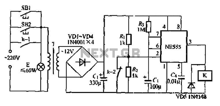
Another application involves the use of a NE555 delay lamp circuit, where components SB1 and SH2 act as J-light buttons that can be installed in two different locations. The lamp can be activated by pressing either SB1 or SB2,...
A safe home is a happy one, but many off-the-shelf surveillance cameras are too expensive or impractical for home use. Designer Alberto Ricci Bitti created an automated and inexpensive surveillance camera that uses a flash card as recording media....
A PIR sensor is triggered when using a timer to wait for 2 seconds after the sensor is activated. Without the timer, the sensor operates as intended. The PIR sensor is connected to an ATMega328p microcontroller, which has three...
Two identical integrated circuits, U1 and U2, known as "hex inverters," are utilized for the primary functions of the theremin. These are CMOS (Complementary Symmetry Metal Oxide Semiconductor) devices commonly employed in digital circuits to perform a logic function...
This project was inspired by a series of QST articles by Hayward, W1PH. The design is based on his April 1962 article, "Have You Tried 160 Lately." The rig features a simple, single-band configuration utilizing 6V6 tubes with regulated...

When the supply voltage drops below a minimum threshold, it is often advisable to disconnect the supply from the system to prevent poor performance or erratic operation. The circuit presented achieves this with minimal cost, board space, and complexity....