
Wideband Active Antenna Circuit

The circuit utilizes a whip antenna, which is a type of monopole antenna known for its simplicity and effectiveness in receiving a wide range of frequencies. The length of the whip antenna is critical; at 30 to 50 cm, it is optimized for the frequency range of interest, allowing for efficient signal reception across the specified bandwidth from 10 MHz to 220 MHz.
The BF981 MOSFET serves as an important component in this design. Its dual-gate configuration allows for better control of gain and frequency response, making it suitable for applications requiring low noise amplification. The high input impedance characteristic of the BF981 ensures minimal loading on the antenna, preserving signal integrity and maximizing the antenna's performance.
In terms of circuit design, the whip antenna is connected to the gate of the BF981, where it acts as the input stage. The output of the MOSFET can be connected to further amplification stages or directly to a receiver, depending on the application. Proper biasing of the MOSFET is essential to maintain its operation in the desired region, ensuring optimal performance.
Additionally, the circuit may include passive components such as resistors and capacitors to filter unwanted signals and stabilize the gain of the MOSFET. Attention should be given to the layout of the circuit to minimize noise and interference, which can significantly affect the performance of the antenna system.
Overall, this antenna circuit is well-suited for applications in radio communications, amateur radio, and other areas where reliable reception of signals in the specified frequency range is required.A 30 to 50 cm whip antenna provides reception from 10 MHz to over 220 MHz. T1 BF981, a dual-gate MOSFET, provides low noise, high-input impedance and high.. 🔗 External reference
Related Circuits

The pressure transmitter circuit data acquisition system utilizes the 1B31, an 18-bit A/D converter (AD1170), and an MCS-51 microcontroller. The configuration, as depicted in the accompanying diagram, features a full-scale output voltage of 10 mV from the pressure transmitter...
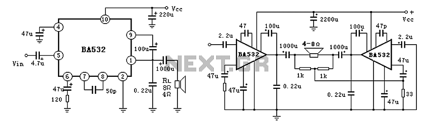
BA532 is a low-frequency power amplifier circuit designed for an output transformerless (OTL) application, capable of delivering up to 5.8W of output power. It features built-in protection against load short-circuits, over-voltage, and over-temperature conditions. The amplifier is housed in...
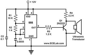
The ultrasonic cleaning machine functions as a humidifier and operates on a simple circuit primarily consisting of an ultrasonic oscillator. It generates ultrasonic frequency signals, typically within the range of 20-40 kHz, using a transistor. These signals are transmitted...
The circuit utilizes a 555 timer configured as a multivibrator, where the oscillation frequency is determined by resistors R1, R2, and capacitor C1. The frequency formula is given by fo = 1.443 / ((R1 + R2) * C1). The...
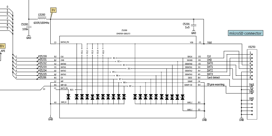
In this tutorial, the functioning of the memory card circuit in mobile phones will be explored. The previous post discussed the pin-outs and types of memory cards utilized in cellular devices. The accompanying block diagram illustrates how the removable...
This homemade metal detector circuit will assist in locating objects made of materials with relatively high magnetic permeability. It is not suitable for detecting certain metals. This metal detector circuit operates on the principle of electromagnetic induction, utilizing a coil...