
Flicker frequency of multiple sets of different light-emitting diode lights chain circuit

The described circuit is a versatile application of the 555 timer IC, operating in astable mode to generate a continuous pulse output. The oscillation frequency is critically dependent on the values of R1, R2, and C1, which dictate the timing characteristics of the circuit. The formula for the frequency fo illustrates that as the resistance values or capacitance increase, the frequency decreases, resulting in a longer pulse duration.
In this configuration, the output from the 555 timer is fed into multiple control transistors (VT1 to VT4). Each transistor acts as a switch that can either allow current to flow through its corresponding light-emitting diode (LED) group or cut off the current, thus controlling the illumination of groups A, B, C, and D. This switching mechanism allows for dynamic control of the LEDs, enabling various lighting patterns or sequences based on the frequency and duty cycle of the output signal.
The circuit can be further enhanced by incorporating additional features such as variable resistors for R1 and R2, allowing for adjustable frequency and duty cycle. Additionally, the use of different types of LEDs can create diverse lighting effects, making this circuit suitable for applications in decorative lighting, indicators, or visual displays. Proper heat dissipation measures should be considered for the transistors depending on the current requirements of the LED groups to ensure reliable operation.It uses multi-vibrator 555 consisting of an integrated circuit, the oscillation frequency Ri, the R2 and Cl decisions (such as group A), fo = 1. 443 / (RI + R2) Cl. By the pulse signal Ai-A4 3-pin output control transistor VTi-VT4 conduction and off, control the light emitting diode groups namely A, B, C, D of turning on and off.
Related Circuits

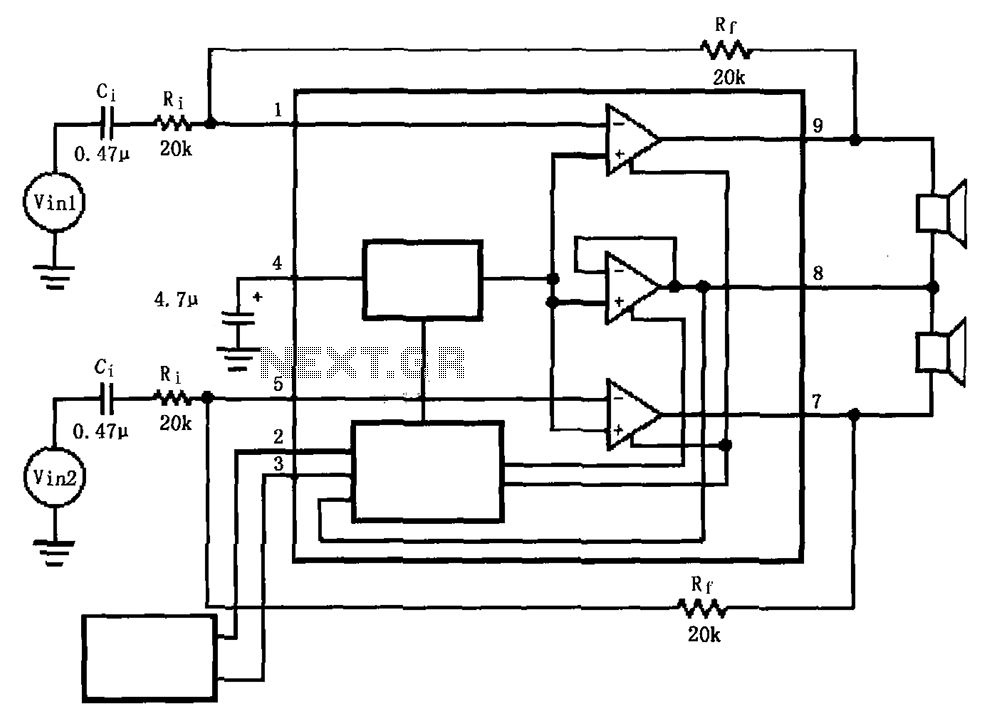
In addition to its primary function as a headphone amplifier, this circuit can be utilized for various applications requiring a wide bandwidth low-power amplifier. It is designed around an operational amplifier (op-amp), with its output current enhanced by a...

The circuit shown in Figure 3-89 illustrates a system where starting motor M1 allows motors M2 and M3 to initiate operation. Upon shutdown, motor Mz can be stopped first; however, once motor M1 is stopped (by pressing switch SB2),...
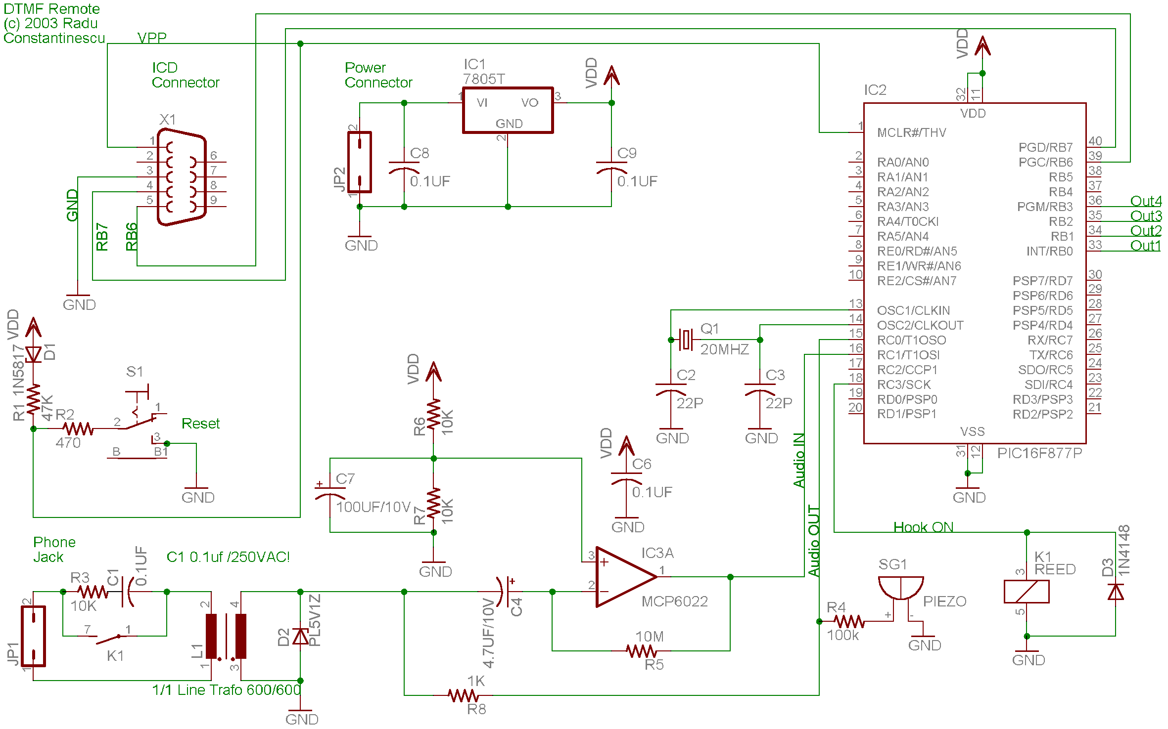
A telephone remote control system allows users to perform various functions remotely using their phone. This system automates complex tasks, simplifying the development and operation of telephone systems. The telephone remote control system is designed to enhance user interaction with...
This is a low-cost 150-watt amplifier circuit with a diagram and schematic design utilizing two Darlington power transistors, TIP142 and TIP147. The 150-watt amplifier circuit is designed to provide high power output while maintaining cost efficiency, making it suitable for...
The LM4911 is presented in a configuration that does not utilize an output capacitor (OCL) for its power circuit. This design eliminates the need for squelch control (Mute), as the shutdown control (SD) responds more rapidly than the squelch...

This circuit is designed to be housed in a compact plastic or preferably metal enclosure, powered by a 9V battery. It features a level control, a male XLR connector (similar to those used in microphones), and a switch. The...