
Wideband Amplifier

The wideband amplifier design leverages the MAR1 IC, which is specifically engineered for high-frequency applications, making it suitable for RF amplification tasks. The +13 dB gain ensures that signals are amplified sufficiently across the specified frequency range, which is critical for maintaining signal integrity in communication systems.
The selection of the load resistor (Rl) is pivotal for regulating the current flowing through the IC. By providing a 17 mA current at a +5 V supply, the amplifier operates efficiently within its designed parameters, ensuring optimal performance. The choice of a 470-ohm resistor for a 12 V supply indicates the need to adjust the load to match the power supply voltage while maintaining the desired current level. This adjustment helps in stabilizing the amplifier's operation and preventing distortion of the amplified signal.
The RF choke (RFC1) plays a significant role in isolating the amplifier from power supply noise, which is crucial for maintaining the amplifier's performance, especially in high-frequency applications. The typical range of 1 to 5 ohms for RFC1 suggests that it is designed to have minimal impact on the circuit's overall impedance while effectively filtering out unwanted signals.
In summary, this wideband amplifier circuit is optimized for high-frequency applications with careful consideration of component values to ensure reliable and efficient operation across a broad frequency spectrum. This wideband amplifier uses a MAR1 IC, which is a gain block. The device is manufactured by Mini-Circuits Lab and offer s + 13-dB gain from dc to 1000 MHz. Rl is selected to provide 17-mA current to Ul at + 5 V. For 12-V supply ^ = 470 . RFC1 is typically 1 to 5 .
Related Circuits
The circuit design aims to create a preamplifier for television systems that operates within the UHF frequency range of 450 MHz to 800 MHz. The preamplifier circuit is essential for enhancing weak television signals before they are processed by the...
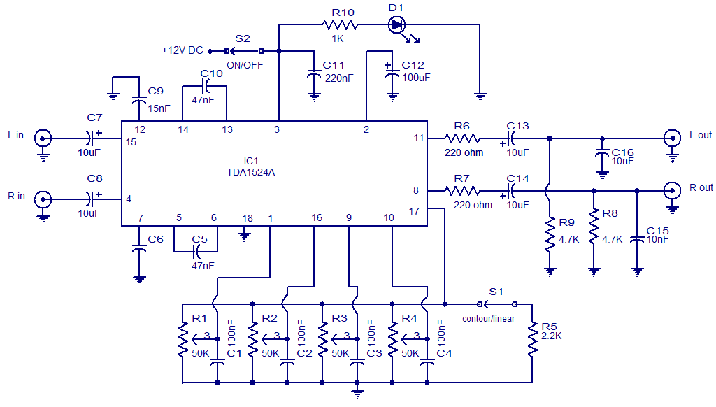
The following circuit illustrates the TDA1524 IC Stereo Preamplifier Circuit Diagram. Features include the ability to control volume, balance, and bass. The TDA1524 is a highly integrated stereo preamplifier IC designed for audio applications. This circuit configuration allows for the...
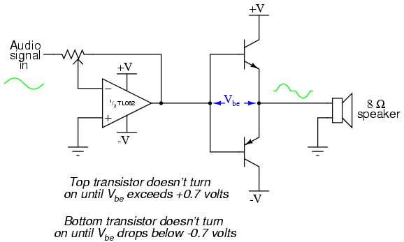
The closer the two transistors are matched, the better the performance. It is advisable to use TIP41 and TIP42 transistors, which are closely matched NPN and PNP power transistors with a dissipation rating of 65 watts each. If a...
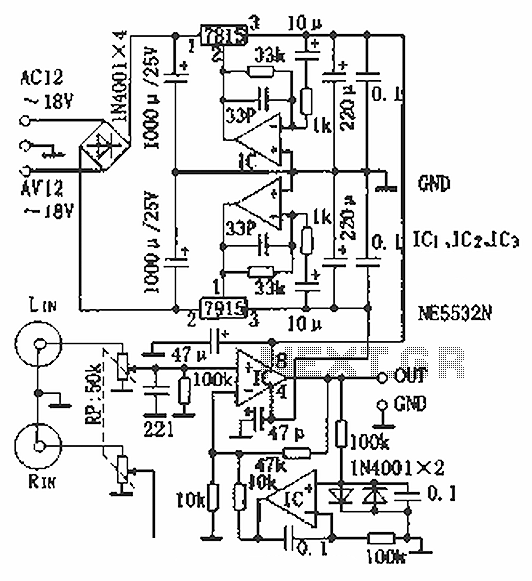
Hi-fi headphones possess a wide frequency response and low distortion, making them incomparable to desktop Hi-Fi audio systems, particularly when compared to some branded headphones and even high-quality speakers. High-fidelity headphones are designed for music listening, offering high resolving...
The MAX2659 low-noise amplifier (LNA) is designed for GPS, Galileo, and GLONASS applications. Manufactured using Maxim's advanced SiGe process, the device achieves a gain of 20.5 dB and an ultra-low noise figure of 0.8 dB, while maximizing the input-referred...
Stationary - MOPLL & Silicon Tuner TUA6020 2 Band TV Tuner Mixer-Oscillator-PLL with balanced IF-Amplifier. The TUA6020 device integrates a digitally programmable Phase Locked Loop (PLL) with a mixer-oscillator block that includes two balanced mixers and oscillators suitable for...