
wideband dtv uhf antenna tv amplifier

The HD TV UHF wideband amplifier is designed to enhance signal reception for television broadcasts in the UHF frequency range, specifically from 400 MHz to 850 MHz. This amplifier is particularly beneficial in regions where the signal strength is insufficient for reliable TV reception. The gain specification of 10 to 15 dB indicates the amplifier's ability to boost weak signals, thereby improving the quality of the received audio and video.
The construction of the amplifier requires careful attention to the physical layout of the components. SMD components, such as capacitors C1, C2, C6, and C7, are utilized for their compact size and efficiency. These components should be soldered onto the printed circuit board (PCB) with minimal lead length to reduce inductance and capacitance, which can adversely affect performance. Shortening the component pins also helps in minimizing potential interference and maintaining signal integrity.
The choice of a metal enclosure for the amplifier is critical. A metal box not only provides physical protection for the components but also acts as a shield against electromagnetic interference (EMI). This shielding is essential in maintaining the amplifier's performance, particularly in environments with multiple electronic devices that may emit unwanted signals. The amplifier should be positioned as close as possible to the TV antenna to reduce the length of the coaxial cable, which can introduce additional losses.
In summary, the HD TV UHF wideband amplifier is a vital component for enhancing TV signal reception in weak signal areas. Its design must prioritize compactness, shielding, and proximity to the antenna to achieve optimal performance. Proper construction techniques, including the use of SMD components and a metal enclosure, are essential for maximizing the amplifier's effectiveness.This HD TV UHF wideband amplifier(Ultra High Frequency amplifier) has a total gain of 10 to 15 dB in the 400 ? 850 MHz domain frequency so it can be used where the tv signal is weak. For this UHF antenna tv amplifier to work correctly you need to cut the components pins as short as possible.
C1, C2, C6, C7 are SMD type ( surface mounted ). This antenna tv amplifier or uhf wideband amplifier need to be build inside of a metal box and then connected close to the tv antenna 🔗 External reference
Related Circuits
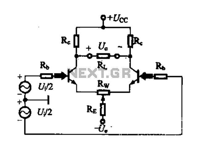
A differential amplifier circuit can be configured in four different connection methods, allowing for a comparison of characteristics such as gain and common-mode rejection ratio (CMRR). This analysis focuses on symmetrical circuits and their performance in handling common-mode signals. The...
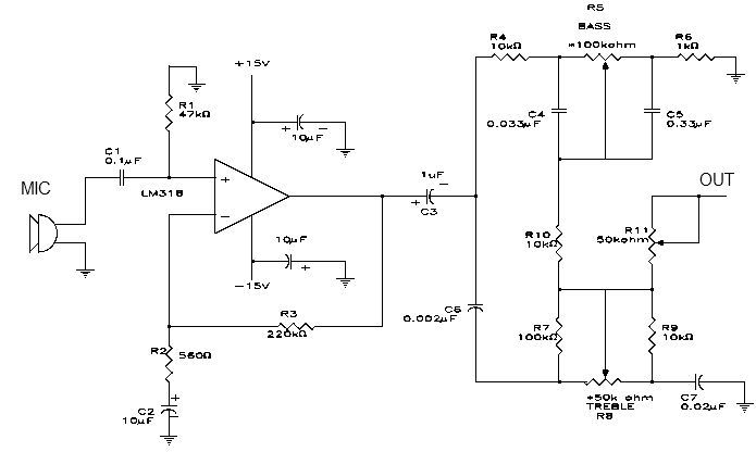
This simple microphone preamplifier is based on the LM318 operational amplifier. The LM318 operates as a standard non-inverting amplifier. Resistor R1 provides a ground input path for the bias current of the non-inverting input. The combination of R2 and...
Utilize a V2-400 subwoofer amplifier for the center channel, and incorporate a separate Digital Converter specifically for the added subwoofer amplifier to initiate a V5.1 system. Place all preamplifiers within the subwoofer enclosure and design a digital control box...
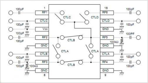
The CYWUSB6953 is a comprehensive Radio System-on-Chip (SoC) device that facilitates the implementation of various simple RF systems using a single chip and a few discrete components. It is specifically designed for low-cost wireless systems that operate within the...
This solid-state push-pull single-ended Class A circuit is capable of providing sound quality comparable to that of valve amplifiers. It delivers an output power of 6.9W when measured across an 8 Ohm loudspeaker cabinet load, with reduced total harmonic...
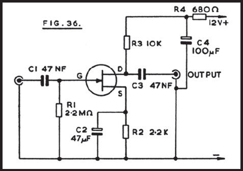
Figure 36 illustrates the circuit of a preamplifier featuring a high impedance input and an output circuit designed for coupling to a main amplifier. This configuration is particularly advantageous for applications such as amplifying the signal from a crystal...