
Wideband high-frequency amplifier

The wideband high-frequency amplifier circuit is designed to operate effectively across a broad frequency range, making it suitable for applications in communications and signal processing. The common emitter configuration is particularly advantageous in this design due to its inherent ability to provide significant voltage gain while maintaining a relatively simple topology.
The circuit includes two transistors, VT1 and VT2, which are configured to work in tandem. The input signal is introduced through a coupling capacitor (C1), which serves to block any DC component while allowing the AC signal to pass. This is crucial for ensuring that the transistors operate within their linear region, thereby avoiding distortion of the amplified signal.
Capacitor C5 plays a vital role in coupling the output of the first transistor (VT1) to the base of the second transistor (VT2). This coupling is essential for cascading the amplification stages and achieving the desired output gain. The choice of capacitors in the circuit, particularly for frequency compensation, is critical. These capacitors help stabilize the amplifier's performance and prevent unwanted oscillations, which can occur at high frequencies.
The output is taken from the collector of the second transistor (VT2), where the amplified signal can be further processed or transmitted. The design allows for tuning the bandwidth by adjusting the values of the capacitors involved, ensuring that the amplifier can maintain a consistent gain across the desired frequency range. The use of high-frequency compensation capacitors is also important in maintaining the integrity of the signal and minimizing phase shifts that could lead to instability.
Overall, this wideband high-frequency amplifier circuit exemplifies the principles of RF amplification, combining careful selection of components and configuration to achieve optimal performance in high-frequency applications.A wideband high-frequency amplifier is shown, the circuit resistance and capacitance coupling of common emitter amplifier can be used to amplify high frequency signals. When th e high-frequency signal Jl end to (input impedance 50 n), applied to the amplifier via a coupling capacitor cl VTI base and amplified by the c5 coupled together to VT2 base, the amplified signal from the collector output. Adjust the band No. capacitor band frequency characteristic can reach l dB, with number of high-frequency capacitor compensation capacitor.
Related Circuits
A straightforward 4-channel video amplifier electronic circuit can be constructed using the NJM2582 integrated circuit, which is suitable for video applications with a SCART connector. The design of this circuit is uncomplicated and requires only a few external electronic...

The Softrock Ensemble RXTX has a 1W output, which is relatively low, so a linear amplifier was constructed to enhance the signal. This amplifier provides 16W output when supplied with a 24V power source (utilizing a 45W switching adapter...
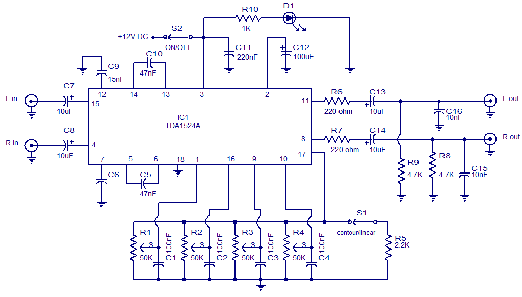
The circuit diagram presents a high-quality stereo preamplifier featuring tone control, utilizing the TDA1524 IC from Philips. This integrated circuit requires minimal external components, operates with low noise, and accommodates a broad power supply voltage range. Potentiometers R1 through...
This original design is a variation on a well-known design, examples of which can be found in a great many texts. My variation was to add a second differential stage to replace the usual common emitter-plus-constant current source. Doing...
This schematic diagram illustrates a 70W power amplifier utilizing MOSFET technology for audio systems. Alternative input stage transistors include the Toshiba 2SA970BL and 2SC2240BL, which serve as suitable substitutes for the Hitachi 2SA1085E. The 70W power amplifier is designed to...
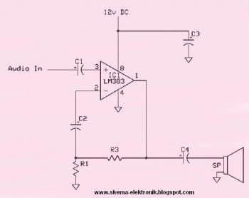
This circuit is an 8W audio amplifier utilizing the LM383 integrated circuit as its primary component. It is designed to be simple, cost-effective, and easy to assemble. Component part list: - C1: 10μF Electrolytic Capacitor - C2: 470μF Electrolytic Capacitor - C3:...