
Wideband Power Amplifier Circuit

The TRW CA-815H is a high-performance amplifier designed for applications requiring moderate gain and wide frequency response. With a gain of 17 dB, it is suitable for use in various RF applications, such as communication systems, signal processing, and instrumentation. The amplifier operates efficiently across a broad frequency range of 10 to 1000 MHz, making it versatile for both narrowband and wideband applications. The output power of 100 mW allows it to drive moderate loads effectively, ensuring signal integrity in transmission lines.
In contrast, the CA-2870 amplifier offers significantly higher performance for specific applications, providing a gain of 34 dB and an output power of 0.4 W. This amplifier is optimized for frequencies between 20 and 400 MHz, making it ideal for applications such as television broadcasting, FM radio, and other communication systems that operate within this frequency range. The increased gain and output power of the CA-2870 allow for improved signal amplification, which is crucial in scenarios where signal strength is critical for maintaining communication quality.
Both amplifiers can be integrated into various circuit designs, including cascaded amplifier configurations and signal conditioning circuits. Proper impedance matching and power supply considerations are essential for maximizing performance and minimizing distortion. Additionally, thermal management techniques should be employed to ensure reliable operation, especially in high-power applications. The selection between the CA-815H and CA-2870 will depend on specific application requirements, including frequency range, gain, and output power needs. Using TRW P/N CA-815H, a 17-dB gain amplifier that delivers 100 mW over 10 to 1000 MHz can be constructed. The CA-2870 will yield 0.4 W with 34-dB gain from 20 to 400 MHz.
Related Circuits

This stereo balance indicator circuit diagram is designed using a few common external components. The schematic circuit is simple to build and provides a visual indication with LEDs for left, right, and center balance. Outputs from each channel are...
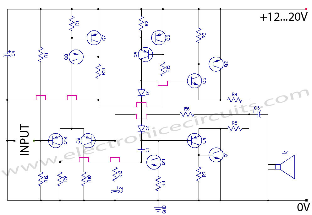
Discrete Class AB Transistor Audio Power Amplifier Circuit Diagram. This is a Class AB transistor power amplifier. It is a simple amplifier to... A Class AB transistor audio power amplifier is designed to provide high-quality amplification for audio signals while...
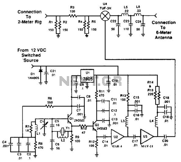
This transverter utilizes the bilateral properties of a balanced mixer to generate a 6-meter output from 2-meter inputs. The component Y1 is a 90-MHz crystal. It is important to note that the input frequency on the 2-meter band is...
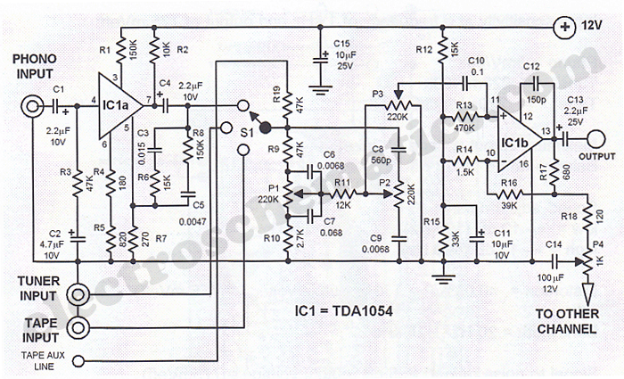
This Hi-Fi stereo preamplifier circuit is designed using the TDA1054 integrated circuit from SGS. The TDA1054 is a 16-pin DIL package that incorporates two separate preamplifier circuits. It is a low-noise preamplifier with minimal complications in the design process....
C1 is a 1000 microfarad aluminum electrolytic capacitor. For loads less than 100mA, a 220 microfarad capacitor can be substituted. The voltage rating should be 2.5 times the output voltage. C1 serves as a critical component in various electronic circuits,...
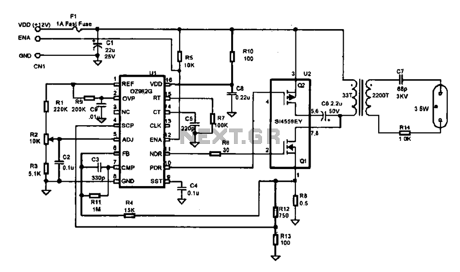
This document describes an efficient inverter control circuit designed for use as an LCD backlight power supply. The circuit is primarily managed by the chip UL (02962G), which interfaces with a driving field-effect transistor (U2), a voltage transformer, the...