
Efficient inverter control circuit

The efficient inverter control circuit described operates as a critical component in providing power to LCD backlight systems. The circuit architecture begins with a +1V DC input, which is filtered through capacitor C1 to ensure a stable voltage supply for the UL (02962G) integrated circuit. This IC serves as the control unit, utilizing a start signal (ENA) to enable or disable the inverter circuit based on operational requirements.
The driving field-effect transistor (U2) plays a vital role in modulating the power delivered to the step-up transformer. When the inverter is activated by the ENA signal, the UL chip produces a pulse-width modulation (PWM) signal at its output pin. This PWM signal controls the switching of the field-effect transistor, allowing it to efficiently manage the energy transfer to the transformer.
The step-up transformer is designed to amplify the voltage generated by the field-effect transistor to approximately 800V. This high voltage is essential for powering the backlight lamp, which illuminates the LCD display. The configuration of the transformer and the associated circuitry is optimized to ensure minimal losses and high efficiency in the energy conversion process.
Overall, this inverter control circuit is engineered to provide reliable and effective power management for LCD backlighting applications, ensuring that the display operates at optimal brightness levels while maintaining energy efficiency.Efficient inverter control circuit It shows a highly efficient inverter control circuit, which is used as the LCD backlight power supply circuit, which is mainly controlled by the chip Ul (02962G), the driving field effect transistor U2, Dan-voltage transformer, the backlight lamp and associated circuitry configuration. After the DC power sent by the +1V DC voltage through the filter capacitor Cl integrated circuit Ul and driving power field-effect transistor; start signal (ENA) will be sent to the U1 feet for controlling the inverter circuit opens, stop.
When the inverter power supply is normal, after receiving the start signal from the Ul of ? foot guard pin output PWM pulse signal interaction, after driving into the field effect transistor amplifier in step-up transformer, the pulse from the step-up transformer voltage up to about 800 V, power supply for the backlight lamp.
Related Circuits
%2Band%2B(US)%2BCX500%2BC%2B1979-81%2Band%2B1979%2BCX500%2BD%2BElectrical%2BWiring%2BDiagram.jpg)
Lamp Electrical Circuit Diagram Manual PDF Download. This document provides a comprehensive manual for downloading the electrical circuit diagram of a lamp. The circuit diagram serves as a crucial reference for understanding the electrical connections and components involved in lamp...
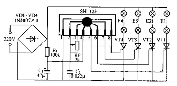
A water Happy Valley-type four flashing lights string controller, electric bollard is designed for use with a type J Ding Japanese lantern. The circuit employs a specific integrated circuit (IC) utilizing CMOS technology. It features a black soft cream...
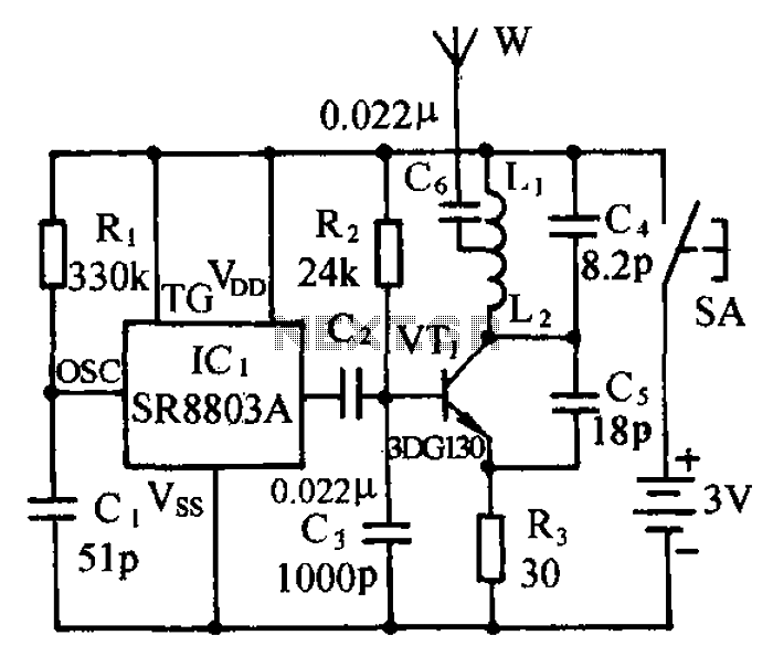
The circuit consists of a language and sound FM transmitter. It is mounted on a 25mm x 35mm PCB, designed to be placed on a table. When activated by pressing the micro switch SA, the circuit transmits an FM...
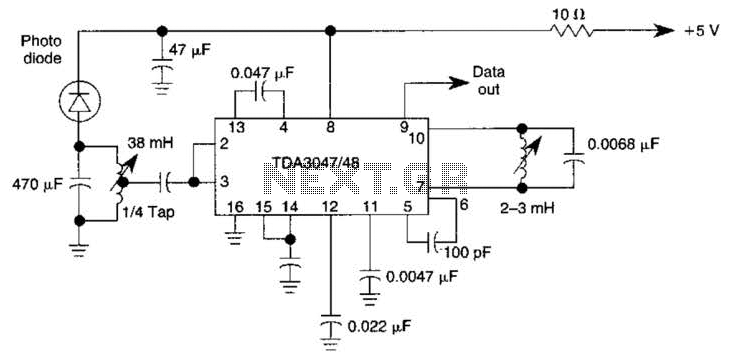
The circuit operates from a 5-V supply and has a current consumption of 2 mA. The output functions as a current source that can drive or suppress a current exceeding 75 mA with a voltage swing of 4.5 V....
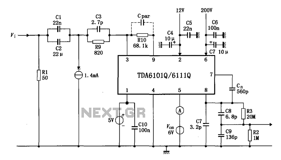
The test circuit features a feedback factor of 1/83 utilizing the DA6101Q/6111Q. The input signal is fed through a network comprising resistors R1 and R9, and capacitors C1, C2, and C3, entering the TDA6101Q, which includes three pins for...
Hens require adequate illumination to increase egg production rates. To counteract the reduced winter sunlight, poultry farms commonly utilize artificial lighting in coops. For instance, the circuit depicted in Figure 297 can automatically provide light at night. The light...