
Wien Bridge Oscillator

The Wien Bridge oscillator is a popular circuit used for generating sine waves. It comprises an operational amplifier configured to provide positive feedback through a bridge circuit formed by resistors and capacitors. The frequency of oscillation is determined by the values of the resistors and capacitors in the feedback loop. In this case, R4 and R5 are the resistors that set the gain, while C1 and C2 are the capacitors that determine the timing characteristics of the oscillator.
The feedback mechanism is crucial for maintaining stable oscillations. The feedback coefficient of 1/3 indicates that the feedback loop is set to provide a fraction of the output signal back to the input, ensuring that the conditions for sustained oscillation are met. The operational amplifier must have a gain greater than three to satisfy the Barkhausen criterion, which states that the product of the gains around the loop must equal one at the frequency of oscillation.
The inclusion of the FET serves a dual purpose: it stabilizes the gain of the oscillator and prevents distortion in the output waveform, which can occur if the gain is too high. The automatic gain control feature allows the circuit to adapt to variations in output amplitude by adjusting the resistance of the FET based on the output voltage level. This dynamic adjustment of gain helps maintain a clean sine wave output, which is essential for applications requiring precise signal generation.
In summary, the Wien Bridge oscillator designed in this experiment effectively utilizes an operational amplifier, passive components, and an FET to produce a stable 1 kHz sine wave output while ensuring that the signal remains undistorted through automatic gain control.In this experiment, an oscillator is constructed using an operational amplifier and some other passive elements. This configuration for the oscillator is called Wien Bridge. The frequency of the oscillator is determined by R4, R5, C1, and C2 elements. In this circuit, they are chosen so that the frequency is 1 khz. The feedback coefficient ( ²) is 1/3 in this circuit, so gain is chosen 3 or higher to fullfill the Barkhausen oscillation criterion. The negative feedback applied using FET+R3 and R6 determines the gain and because of very existence of the FET, the output won`t be clipped.
The FET works as an AGC: when the output voltage decreases, the magnitude of the negative voltage on the gate of the FET increases, causing its resistance Rds to increase and therefore decreasing the gain of the oscillator ( 1+R6/(R3+Rds) ). This decrease in the gain causes the output not to clip. 🔗 External reference
Related Circuits
Figure a illustrates a multivibrator circuit capable of generating a square wave signal. Figure b depicts a flip-flop circuit that utilizes the falling edge of the input signal to produce a trigger pulse signal. Figure c represents a monostable...
This Wien bridge oscillator utilizes an incandescent lamp to stabilize its amplitude. The amplitude stabilization results in a low distortion output and supports multiple frequencies. The Wien bridge oscillator is a type of electronic oscillator that generates sine waves. It...
Electronics tutorial about the RC oscillator circuit, RC phase shift oscillators, and how a tuned RC oscillator circuit produces sine waves. The RC oscillator circuit is a fundamental electronic circuit used to generate oscillating signals, particularly sine waves. This circuit...
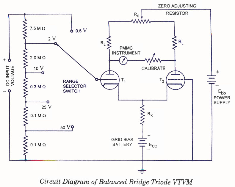
Voltmeters can be utilized for measuring both direct current (DC) and alternating current (AC) voltages and are widely used. These voltmeters are available in two types: vacuum tube and transistorized. In the vacuum tube version, two identical triodes, T1...
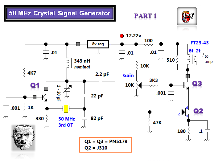
The initial tasks involved acquiring VHF components and investigating the Butler crystal oscillator, particularly focusing on the common base variant. The VHF knowledge base is rich with established information. There are claims that the emitter follower variant of the...
Will an LC-based oscillator be able to demonstrate performance comparable to crystals under such conditions (possibly in unusual configurations like LC-opamp) so that any energy loss at each stage is recovered, resulting in a narrower bandwidth? Examine some amateur...