
RC Oscillator Oscillator Tutorial

The RC oscillator circuit is a fundamental electronic circuit used to generate oscillating signals, particularly sine waves. This circuit typically employs resistors (R) and capacitors (C) to create a feedback loop that enables continuous oscillation. The RC phase shift oscillator is a specific type of RC oscillator that utilizes a network of resistors and capacitors to produce a phase shift of 180 degrees, which is essential for sustaining oscillations.
In the basic configuration of an RC phase shift oscillator, three or more RC stages are used to achieve the required phase shift. Each RC stage contributes 60 degrees of phase shift, amounting to a total of 180 degrees when combined with the 180-degree phase shift provided by an inverting amplifier, such as a transistor or an operational amplifier. The output frequency of the oscillator can be determined by the values of the resistors and capacitors used in the circuit.
The tuned RC oscillator circuit, on the other hand, is designed to produce sine waves with a specific frequency. This is achieved by tuning the circuit to resonate at a desired frequency, often using an inductor along with the RC components. The resonance condition enhances the amplitude of the output sine wave, making it suitable for applications that require stable and pure sine wave signals.
In summary, RC oscillators, particularly the phase shift and tuned types, are critical components in various electronic applications, including waveform generation, signal modulation, and clock generation in digital circuits. Understanding the principles behind these oscillators is essential for designing effective electronic systems that require precise frequency control and signal integrity.Electronics Tutorial about the RC Oscillator Circuit, RC Phase Shift Oscillators and how a Tuned RC Oscillator Circuit produces sine waves.. 🔗 External reference
Related Circuits
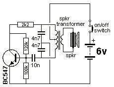
The Colpitts Oscillator is characterized by tapping the mid-point of the capacitive side of the oscillator section. The inductor can be the primary side of a speaker transformer. The feedback comes via the inductor. The Colpitts Oscillator is a type...
An op-amp based Colpitts oscillator in Multisim displays a "timestep too small" error when the run button is pressed. Despite extensive research and attempts to resolve the issue, the error persists. The design features a C-L-C pi circuit that...
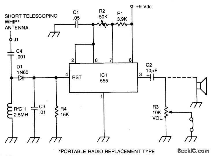
A sidetone oscillator is a specialized audio oscillator that is activated and deactivated in conjunction with the transmitter. This oscillator is driven by RF signals and is powered by batteries. It employs a 555 integrated circuit (IC) timer configured...
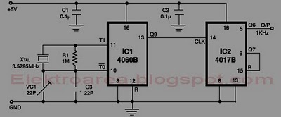
This circuit is designed for accurate time-base generation utilizing the commonly available 3.5795 MHz crystal, which is frequently used in telecommunication equipment. A crystal-based oscillator combined with a divider IC chain or a similar circuit, such as an ASIC,...
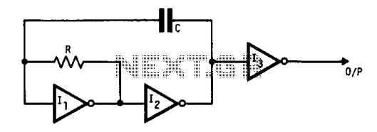
This oscillator utilizes standard inverters, one resistor, and one capacitor, and it does not have a minimum operating frequency. The resistor (R) and capacitor (C) must be selected to ensure that the currents flowing into the gates remain below...
The circuit produces a clean sine wave signal suitable for audio testing or other applications requiring a high-quality sine voltage source. It utilizes a widely available dual operational amplifier, the Texas Instruments TL072CP. The component values yield an output...