
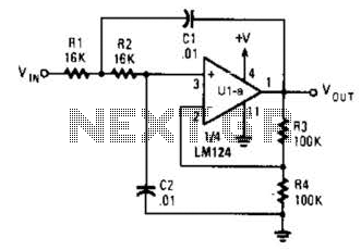
50kHz FM optical receiver circuit

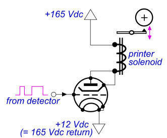
The impulse speed modulation system described operates by manipulating the frequency of light pulses transmitted through an optical fiber. The transmitter is designed to modulate the light beam at a center frequency of approximately 50 kHz, which is crucial for maintaining effective communication over optical fibers. The modulation process involves varying the speed of the light pulses, which encodes the information to be transmitted.
The L14G2 optical transistor plays a pivotal role in this system by converting the modulated light signal into a radio-frequency (RF) signal. This conversion is essential for demodulation, as RF signals are easier to process and analyze than optical signals. The demodulation process involves extracting the original audio frequency signal from the RF signal, which is accomplished using appropriate demodulation techniques.
In summary, this circuit integrates optical and radio-frequency technologies to achieve effective impulse speed modulation and signal recovery, making it suitable for applications in telecommunications and data transmission systems. The combination of optical transmission and RF processing enhances the efficiency and reliability of the communication system.This circuit is used in impulse speed modulation system. In this system, transmitter change impulse speed of modulated beam in optical fiber, let it change around 50kHz center frequency. L14G2 optical transistor convert molulated light to radio-frequency signal. The radio-frequency isusedfor demodulating. It can recover original audio frequency signal.. 🔗 External reference
Related Circuits
The PIC16C57-RCT is a communication single-chip microcomputer integrated circuit that is commonly utilized in the Qiao Xing series of IC card management telephones. The PIC16C57-RC integrated circuit features a pulse and dual-tone dialing circuit, memory data and clock circuit,...
The circuit operates in a parallel-fed configuration, as the DC plate current does not pass through the inductor. R3 can be substituted with an RF choke if desired. Capacitor C3 prevents B+ from appearing across the variable capacitor, which...
The circuit presented has a cutoff frequency of approximately 1 kHz. The resistors R1, R2, and capacitors C1, C2 can be adjusted to achieve any desired frequency. The circuit is designed as a filter, likely a low-pass or high-pass filter,...

This design outlines a simple wideband output amplifier suitable for use as a 50-ohm transmission line driver. The circuit is constructed using the CA3140 operational amplifier. When utilized alongside the function generator and sine wave shaper circuits, it delivers...
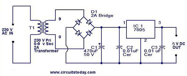
A 5V power supply using IC 7805 is designed and explained with a neat circuit diagram. The circuit for a 5V power supply utilizing the IC 7805 voltage regulator is a straightforward and efficient design that provides a stable output...
The 900 Hz tone is generated using an LC oscillator. The inductive component, "L," is provided by the inductance of the oscillator's output coupling transformer T1. This configuration is a variation of one of the two standard Hartley oscillator...