
timer 555 schematic

The Simple Timer circuit using the 555 timer is a versatile and straightforward design suitable for various applications, including automatic lighting systems, delay timers, and pulse generation. The 555 timer operates in monostable mode, meaning it outputs a single pulse when triggered. Upon pressing switch S1, the circuit transitions to its active state, and the timing begins. The duration of the output pulse is controlled by the RC time constant, which is a product of the resistance (R) and capacitance (C) values in the circuit.
In this configuration, the variable resistor (VR1) allows for adjustable timing, enabling users to set the desired duration of the output pulse. The capacitor (C) stores charge and discharges through the resistor, determining how long the output remains active. The choice of components is crucial for achieving precise timing; thus, using a tantalum capacitor, known for its stability and low leakage current, alongside a high-quality resistor, ensures minimal deviation from the expected timing.
The relay output can handle AC loads, making this circuit applicable for switching devices such as lamps or motors. The selection between normally closed and normally open connections allows for flexibility in design, depending on whether the load should be activated or deactivated upon triggering the timer. The circuit can be powered by a DC supply within the specified voltage range, making it adaptable for various electronic projects. Overall, the Simple Timer circuit with a 555 timer is an effective solution for timing applications in both hobbyist and professional electronic designs.Simple Timer With 555 is one example of a simple timer and can be applied to electronic equipment. With 555 Timer Simple series takes advantage of the mode of the IC monostable multivibrator 555. With the relay output control circuit can be used to control equipment with AC voltage source. With 555 Timer Simple circuit can work with source voltage of 5 - 12VDC depending on the relay used. In order to use Simple Timer With this 555 can be started by pressing the switch S1 to start the process of timing. In the relay there are 2 options that is normaly Close connection (NC) and normaly open (NO). The duration of the timing circuit 555 Simple Timer With RC configuration is determined by the VR 1 MOhm and C 10uF.
Active timer duration can be calculated with the formula T = 1. 1 RC where T (seconds), R (Ohm) and C (farad). To get more accurate results R and C components referred to in the formula should use good quality components, namely C of tantalum material and R with the quality of 1%. 🔗 External reference
Related Circuits
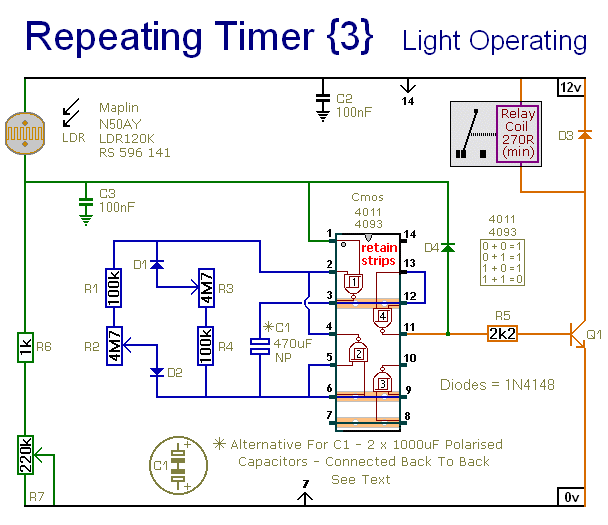
This circuit closely resembles Repeating Timer No. 2. However, the inclusion of a light-dependent resistor (LDR) allows the timer's operation to be confined to daylight hours. Resistor R7 enables the adjustment of the light level at which the timer...
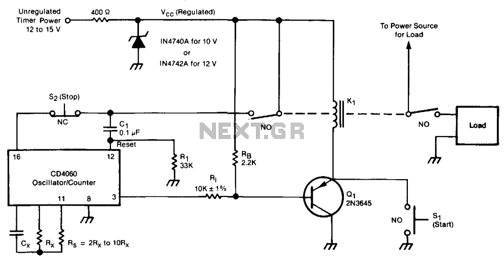
The timer consists of an oscillator and a counter integrated into a single circuit. The timing interval is calculated by multiplying the oscillator period by the number of cycles to be counted. The frequency of the oscillator is influenced...
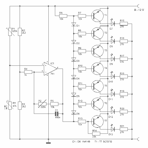
This digital thermometer indicates the temperature measured with an NTC using 7 LEDs. The circuit works using an opamp, the well-known 741, which amplifies the voltage difference between its plus and minus input. This amplification (sensitivity) can be set...
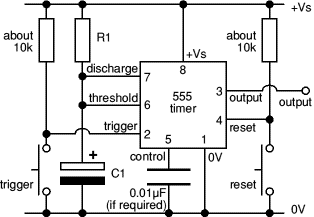
The 8-pin 555 timer is one of the most versatile integrated circuits (ICs) available, utilized in numerous projects. With minimal external components, it can be employed to construct various circuits, many of which do not pertain to timing applications....
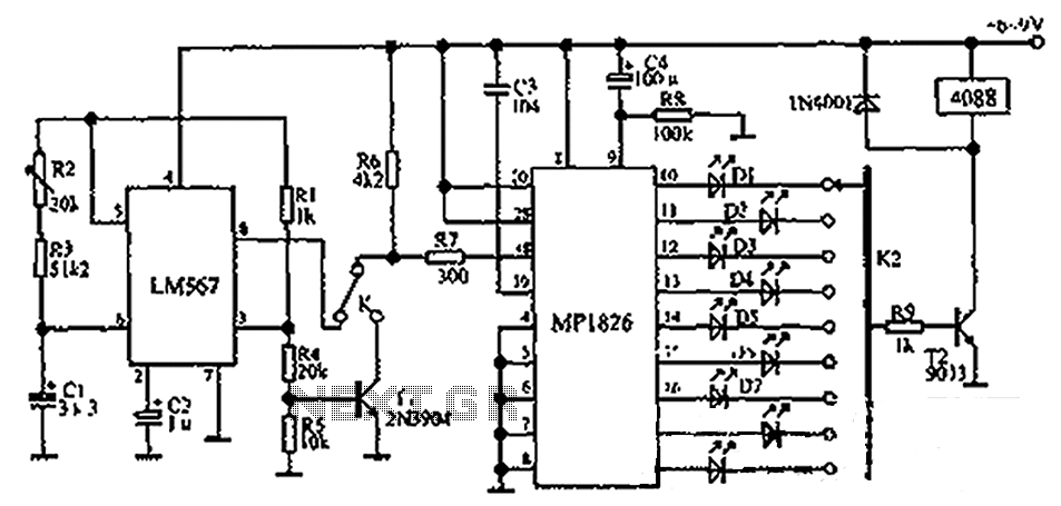
The circuit illustrated in the figure incorporates the MP1826 as a multi-stage divider. The LM567 serves as the frequency demodulation component, functioning as a dual-band oscillator that generates the desired low-frequency pulse from the MP1826. The oscillation center frequency...
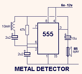
This circuit detects metal and also magnets. When a magnet is brought close to the 10mH choke, the output frequency changes. The circuit operates on the principle of inductance variation in response to the presence of a magnetic field. The...