
Wien bridge sine wave oscillator circuit composed of LM101A

The Wien bridge oscillator is a well-known electronic circuit utilized for generating sine waves. It employs a combination of resistors and capacitors to create a feedback loop that allows for sustained oscillations. The circuit operates on the principle of balancing the gain and feedback to achieve a stable oscillation frequency.
In this configuration, the FET plays a crucial role in controlling the negative feedback. Its internal resistance varies with the gate voltage, which is influenced by the output voltage of the oscillator. When the output amplitude exceeds a specific threshold, the feedback mechanism activates the transistor Q2, which subsequently alters the gate voltage of Q1, effectively regulating the output amplitude. This automatic gain control feature is essential for maintaining the oscillator's stability and preventing distortion.
The positive feedback loop, formed by components C1, C2, R1, and R2, is critical for initiating and sustaining oscillations. The values of these components must be carefully selected to ensure that the phase shift around the loop is precisely 360 degrees, which is necessary for oscillation. The calculated oscillation frequency of approximately 1.6 kHz indicates that this circuit is suitable for applications requiring low-frequency sine wave generation.
In practical implementations, the addition of a 100kΩ resistor between the drain and gate or gate and source of the FET is significant. This resistor helps to maintain the FET's operation within its linear region, thereby minimizing harmonic distortion and ensuring a cleaner output waveform. The overall design of the Wien bridge oscillator makes it a versatile choice for audio signal generation, testing, and other applications where stable sine wave outputs are required.The chart shows the Wien bridge sine wave oscillator circuit. The amount of negative feedback circuit is determined by the internal resistance of FET. When the peak value of oscillator output reaches the regulated voltage of regulator diode D1, Q2 turns on, then the grid of Q1 FET becomes negative, Q1`s drain - source resistance increases, the neg ative feedback increases, loop gain decreases. Similarly, when the oscillation amplitude decreases, the loop gain will increase, therefore, it can maintain a certain output range. C1, C2, R1 and R2 constitute a positive feedback loop to ensure the circuit oscillation. Connecting a l00k © resistor between drain and gate or gate and source of FET will ensure the FET working in the linear region and reducing distortion.
Circuit oscillation frequency: f0 = 1/2. According to the component value of the figure, the oscillation frequency R1C1 is calculated approximately 1. 6kHz. 🔗 External reference
Related Circuits
With this counter you can count laps for example (in conjunction with the Simple light trap). The circuit uses two TTL ICs 74LSxx the series. The left IC is a decimaalteller. The input pulses 14 are counted and converted...
The circuit schematic below represents a method for designing an audio mixer. The active component is an LM318, although any operational amplifier could be used in its place. The circuit is a classic design for an operational amplifier summing...
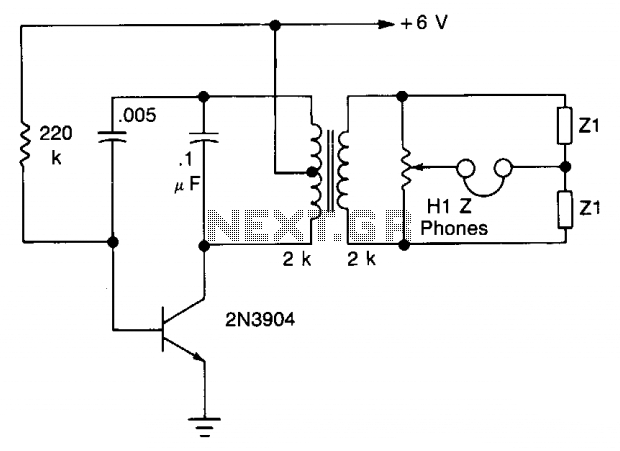
The transistor is configured as an audio oscillator, utilizing an audio transformer in the collector. The secondary winding is connected to a linear potentiometer. The ratio between the two sections of the potentiometer from the slider is proportional to...
This page is provided to the domain owner free by Sedo's Domain Parking. Disclaimer: The domain owner and Sedo maintain no relationship with third-party advertisers. References to any specific service or trademark are not controlled by Sedo or the...
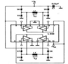
This circuit illustrates a basic configuration for driving a bipolar stepper motor using either an L293 or an L298N driver. It demonstrates that a single device can control a two-phase bipolar stepper motor. The circuit employs either the L293 or...
This is a solar tracking circuit designed to harness power from sunlight. The circuit operates optimally by maximizing sunlight exposure to generate electricity. The solar tracking circuit utilizes a combination of photovoltaic (PV) cells, sensors, and a microcontroller to adjust...