
Wien oscillator

To construct a sine wave generator using a Wien bridge oscillator configuration with the TL082 operational amplifier, the following components are essential: two resistors (R1 and R2), two capacitors (C1 and C2), and a variable resistor (Rf) to form the feedback network. The values of R1 and R2 should be equal to ensure the feedback loop maintains the desired frequency of oscillation, while C1 and C2 should also match in value to establish the correct phase shift for sine wave generation.
The circuit operates by balancing the gain of the op-amp with the feedback resistance Rf. The Wien bridge oscillator requires a gain of 3 to sustain oscillation. Therefore, Rf must be adjusted carefully to achieve this gain without causing distortion. A typical configuration would use R1 and R2 values in the range of 10kΩ, paired with capacitors C1 and C2 of 10nF, resulting in a frequency of approximately 1.59 kHz.
The use of a 1kΩ linear potentiometer as Rf allows for fine-tuning of the feedback gain. However, if oscillation ceases at a low resistance setting, it indicates that the gain is insufficient, necessitating a smaller potentiometer in series to allow for a more precise adjustment. The filament bulb's non-linear resistance characteristics can influence the circuit's stability, so ensuring that it operates within a current range that allows for visible light emission is critical.
In conclusion, careful selection of component values and adjustments of the feedback resistor are vital in achieving a stable and accurate sine wave output. The use of matched components and fine-tuning the feedback loop will help mitigate distortion and enhance the performance of the sine wave generator.Build a sine wave generator. I use this schematic:. The op-amp I have used is the TL082 and the power supply of 9V. However, I do get a nasty sound, indicating that I am not getting a sine wave but rather a distorted waveform. Any idea why this is happening Do you know any list of components for the wien oscillator that can generate accurate sine waves Note that the explanation is
that the self heating causes the resistance of the bulb to stabilise at around Rf/2. You need to choose Rf such that Rf/2 is an achievable resistance for the filament at a reasonable (small) current. I am trying to build a sine wave generator. I use this schematic:. The op-amp I have used is the TL082 and the power supply of 9V. However, I do get a nasty sound, indicating that I am not getting a sine wave but rather a distorted waveform.
Any idea why this is happening Do you know any list of components for the wien oscillator that can generate accurate sine waves Thanks Dave and Steve! I bought a linear 1k potentiometer to use as Rf, but I`m still not getting a sine (I keep getting the nasty sound).
The bulb I am using is 12V 65mA. Is the small current in the fillament enough to cause the bulb to emit visible light At what point in the travel of the 1k trimpot does oscillation cease If it is right up against the end stop (near zero ohms) then you should replace the trimpot with one of a much smaller resistance. The correct adjustment of the 1k pot is somewhere between the point where there is no sustained oscillation and where the output is a square wave.
You see one of these extremes, do you see the other It may even help to place a smaller value trimpot in series with a larger one so you have expanded control around the critical point. The critical point may vary slightly between ranges. The latitude in adjustment (caused by the non-linear nature of the bulb) should allow you to find a setting which works for all ranges.
🔗 External reference
Related Circuits
A simple crystal oscillator can be constructed using a comparator from the LT1720/LT1721 series; however, this design may encounter several inherent limitations and issues. While the LT1720/LT1721 provides the correct logic output when one input falls outside the common...
A voltage-controlled oscillator (VCO) is an oscillator whose frequency is regulated by a voltage signal. The VCO discussed here can generate both triangular and square wave outputs. The control voltage can be adjusted between 5 mV and 5 V,...
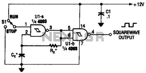
Two gates of the Quad 4093 are utilized to create an oscillator. The resistor (R) can range from approximately 5 kΩ to around 10 kΩ. The capacitor (Cx) can vary from about 10 pF to higher values, with the...
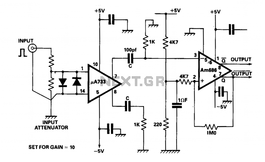
The output of a video amplifier is differentiated before being fed to a Schottky comparator. The propagation delay is typically reduced to 10 ns. The output pulse width is determined by the value of C, 10 pF, resulting in...
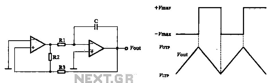
This circuit utilizes two operational amplifiers configured as triangular wave oscillators. It demonstrates a practical application of a relaxation oscillator that employs a voltage comparator to execute the switching function. The schematic in FIG. 2 illustrates the composition of...
The circuit produces a clean sine wave signal suitable for audio testing or other applications requiring a high-quality sine voltage source. It utilizes a widely available dual operational amplifier, the Texas Instruments TL072CP. The component values yield an output...