
Wind battery Charger

The described circuit employs a DC motor functioning as a generator, with its output voltage varying according to the rotational speed (RPM). The LTC1042 integrated circuit serves as a voltage monitoring and control unit, ensuring that the system operates within safe parameters.
When the generator's voltage output drops below the threshold of 13.8 V, the LTC1042 engages the control circuit, enabling the charging of a Ni-Cad battery through the LM334 current source. This current source is designed to provide a constant current output, which is essential for safely charging the Ni-Cad battery while preventing overcharging. During this phase, the lead-acid battery remains inactive and does not receive any charge.
As the generator voltage rises and enters the range of 13.8 V to 15.1 V, the system transitions to charging the 12 V lead-acid battery at a regulated rate of approximately 1 amp/hour. This charging rate is controlled by a power FET, which acts as a switch to manage the flow of current to the battery, ensuring that it does not exceed the safe charging limits.
In scenarios where the generator voltage exceeds 15.1 V, which may occur due to high wind speeds or if the lead-acid battery is fully charged, the LTC1042 automatically connects a fixed load to the generator. This load serves to limit the RPM of the generator, thereby preventing potential mechanical damage that could arise from excessive speeds.
This wind-powered charging system is particularly advantageous in remote locations where wind energy is abundant. It can be effectively utilized in applications such as sailboats or remote radio repeater sites, providing a reliable power source. Unlike solar panels, this system maintains functionality during inclement weather and at night, making it a versatile option for energy generation in diverse environmental conditions. The design ensures both the safety of the batteries and the longevity of the generator by incorporating intelligent monitoring and control mechanisms.The dc motor is used as a generator with the voltage output being proportional to its rpm. The LTC1042 monitors the voltage output and provides the following control functions. If generator voltage output is below 13.8 V, the control circuit is active and the Ni-Cad battery is charging through the LM334 current source. The lead acid battery is not being charged. If the generator voltage output is between 13.8 V and 15.1 V, the 12 V lead acid battery is being charged at about 1 amp/hour rate (limited by the power FET).
If generator voltage exceeds 15.1 V (a condition caused by excessive wind speed or 12 V battery being fully charged) then a fixed load is connected limiting the generator rpm to prevent damage. This charger can be used as a remote source of power where wind energy is plentiful such as on sailboats or remote radio repeater sites.
Unlike solar powered panels, this system will function in bad weather and at night.
Related Circuits

The battery should charge up to 14 volts. A reading of 10.7 volts indicates that one cell is shorted. A good way to diagnose this further is to look at the water level in the cells. The shorted cell...
This document explains the adaptation of a standard 40 amp car relay, converting it from a "normally open" contact configuration to a "normally closed" contact configuration. While it is possible to perform this modification, automotive relays with "normally closed"...
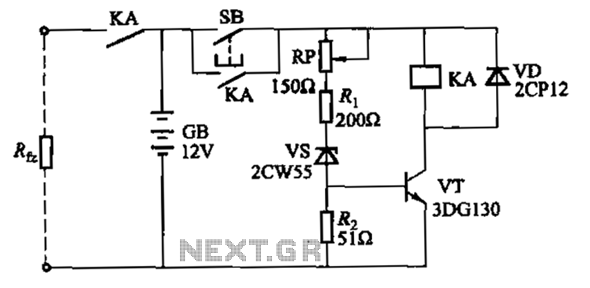
Deep discharge of a battery can lead to plate curing, which shortens the battery's lifespan. To prevent this, a discharge protection device can be implemented. The circuit diagram illustrates this mechanism. When the battery voltage falls to a predetermined...
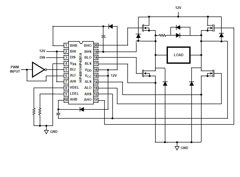
An individual is experiencing an unusual issue while utilizing an Intersil HIP4081A H-bridge driver integrated circuit (IC). The IC is connected to an Arduino microcontroller unit (MCU). The Intersil HIP4081A is a high-performance H-bridge driver designed for driving DC motors...
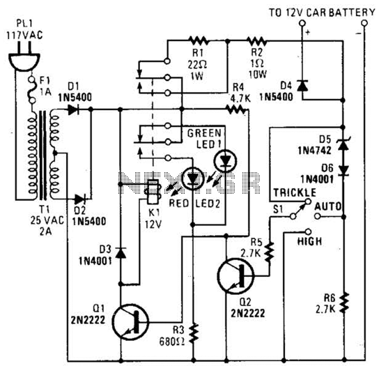
The circuit is capable of supplying either a trickle charge (50 mA) or a high-current charge (1 A). Users can select either charging method or an automatic mode that initially trickle charges a battery if it is particularly low...
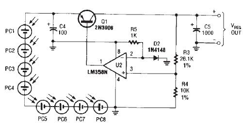
The circuit diagram illustrates a portable solar charger that utilizes an LM358N operational amplifier and a single transistor. This regulator delivers a constant output of 2.4 volts DC, suitable for powering small devices requiring energy from two AA battery...