
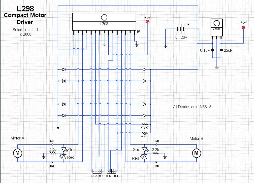
Motor Driver works with PS not battery

The Intersil HIP4081A is a high-performance H-bridge driver designed for driving DC motors and other inductive loads. It features a dual high-side and low-side driver configuration, which allows for efficient control of motor direction and speed. The driver IC can handle high voltage and current levels, making it suitable for various applications, including robotics and automation systems.
When interfacing the HIP4081A with an Arduino MCU, it is essential to ensure proper connections between the two components. The Arduino should provide the necessary control signals to the H-bridge driver, typically through digital output pins. The H-bridge will then control the power delivered to the motor based on these signals.
Key considerations for troubleshooting issues with the HIP4081A include checking the power supply levels to ensure they meet the specification requirements of the IC, verifying the integrity of the connections between the Arduino and the HIP4081A, and ensuring that the control signals from the Arduino are being correctly interpreted by the driver. Additionally, it is important to review the motor specifications to ensure that they are compatible with the driver capabilities.
In cases where unexpected behavior occurs, such as erratic motor operation or failure to respond to control signals, examining the circuit layout for potential ground loops or interference is advisable. Furthermore, utilizing an oscilloscope to monitor the output signals from the HIP4081A can provide insight into the operational status of the driver and the motor. Proper thermal management should also be considered, as excessive heat can lead to performance degradation or failure of the driver IC.Hi Guys, first post to the forum here. I`m having a strange issue using an Intersil HIP4081A H bridge driver IC. I have it hooked up to an Arduino MCU .. 🔗 External reference
Related Circuits

This is a low-power voltmeter circuit designed for use with alternative energy systems operating on 12V and 24V batteries. The voltmeter features an expanded scale that displays small voltage increments within the 10 to 16V range for 12V batteries...
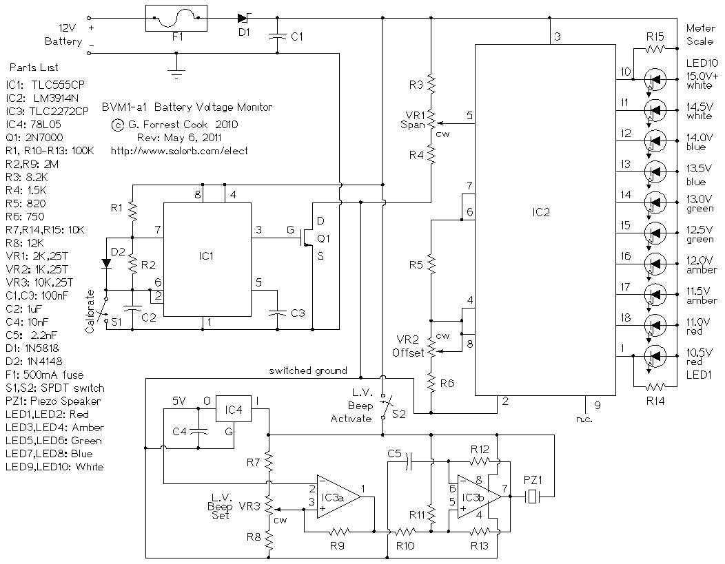
This circuit provides an audible and visual low voltage warning for 12V battery powered devices. When the battery voltage is above the set point (typically 11V), the circuit is idle. If the battery voltage should fall below the set...
The ArduinoISP Bootloader/Programmer Combination Shield (not displayed) works with an Arduino equipped with a USB to serial chip (e.g., Arduino Uno) to upload the bootloader and sketches to a DIYduino. A USB to Serial programmer can also be utilized...
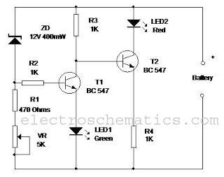
This circuit monitors the charging process of a 12 Volt Lead Acid or Tubular battery. The LED status indicates whether the battery is charging and signals when it reaches a full charge. It can be integrated into various battery...
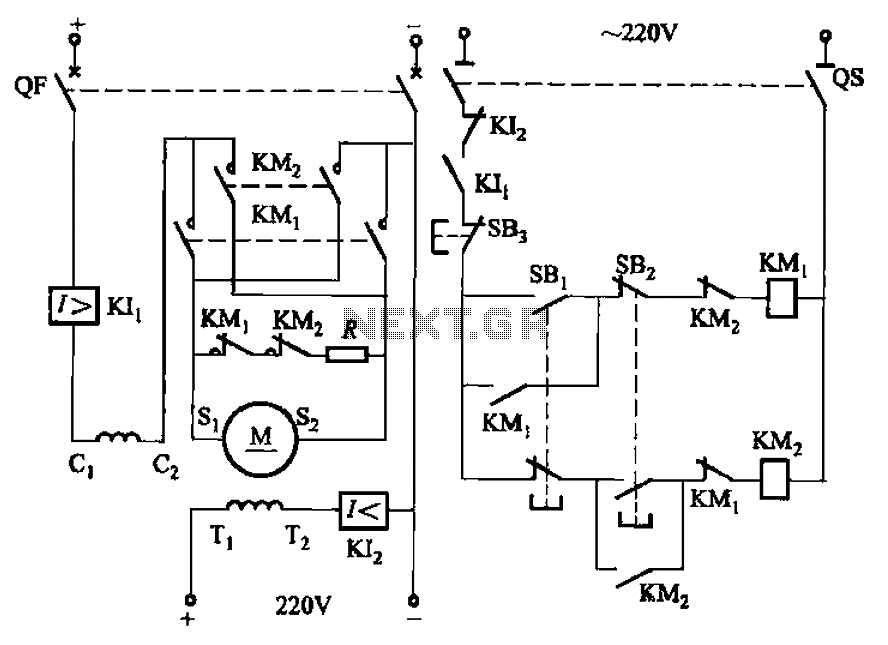
The circuit depicted in Figure 3-194 features a re-excitation type DC motor with six terminals: S1 and S2 for the armature windings; C1 and C2 for the series excitation (field) windings; and T1 and T2 for the shunt (field)...
The growth of high-definition and digital cable services, once a primary driver for expansion, is now beginning to slow. This trend coincides with the increasing use of applications on personal computers (like Skype and magicJack) and smartphones. Even the...