
Winding electronic counter 2

The winding machine's electronic counter is designed to accurately measure and display the number of turns made during the winding process. The power circuit supplies the necessary voltage and current to the entire system, ensuring stable operation. The infrared switch circuit serves as a sensor to detect the position of the coil, triggering the counting mechanism each time a complete turn is made.
The shaping/transformation circuit processes the signals received from the infrared switch, converting them into a suitable format for counting. This circuit may include components such as operational amplifiers or Schmitt triggers to ensure clean and reliable signal transitions. The reset circuit allows the user to set the counter back to zero, providing flexibility for multiple winding operations without manual intervention.
The divider circuit is crucial as it can scale down the input signals to the appropriate level for the LED counter. This ensures that the counter can accurately reflect the number of turns, especially in applications where the coil may be wound rapidly. Finally, the LED counter visually presents the data, allowing operators to monitor the winding process in real-time.
Overall, the design of the winding machine electronic counter integrates multiple circuits to achieve precise measurement and user-friendly operation, making it an essential component in automated winding applications.The winding machine electronic counter described in the example uses LED digital display to show the wound coil turns, the use of maximum count rate is 9900 turns. The working principle The winding machine circuit is composed of the power circuit, infrared switch circuit, shaping / transformation circuit, reset circuit, divider circuit and the LED counter..
🔗 External reference
Related Circuits
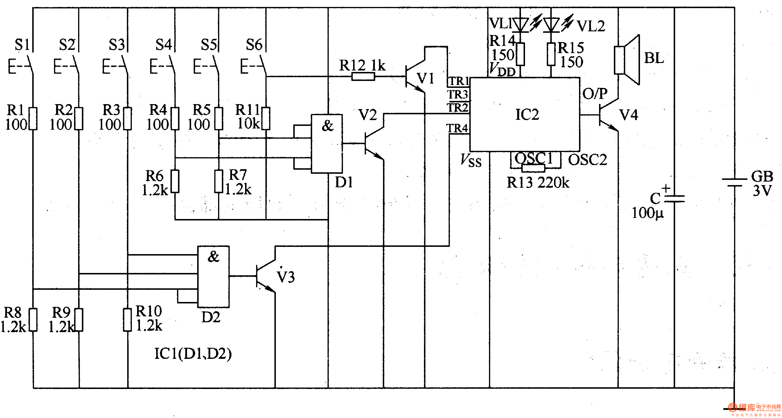
The three-tone electronic doorbell circuit includes a coding trigger circuit, a multi-tone generator, and an audio amplifier circuit, as illustrated in Figure 3-110. The coding trigger circuit is made up of buttons S1-S6, two four-input AND gates (D1, D2)...
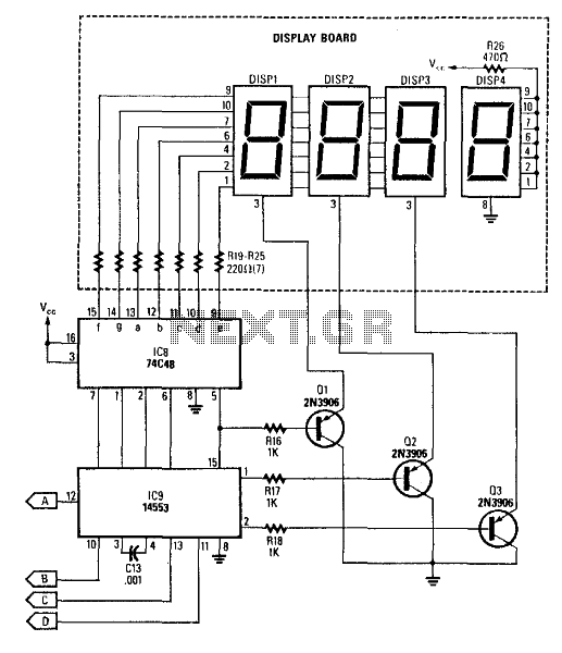
This circuit produces a readout for the digital tachometer circuit. IC9 is a 3-digit LED display driver, counter, and latch. IC8 drives the common-cathode LEDs, which are enabled by Q1, Q2, and Q3. See page 268, Fig. 46-5 for...
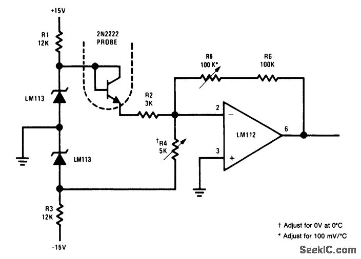
This simple circuit is an electronic thermometer that utilizes an inexpensive silicon transistor (2N2222) as the temperature sensor. The circuit provides an accuracy of better than 1°F over a 100°F range. An LM113 diode regulates the input voltage to...
Alternative display methods exist beyond the original 8 LED frequency counter, potentially offering improved readability and a more suitable format for QRP equipment. This document presents examples of binary decimal displays. Typically, the counter omits the MHz position, focusing...
This project takes advantage from -HOLD input, which is connected to push-button P1. As long as the -HOLD input is low, truth table's timeouts have no effect because this input serves to disable any state change provoked by timers....
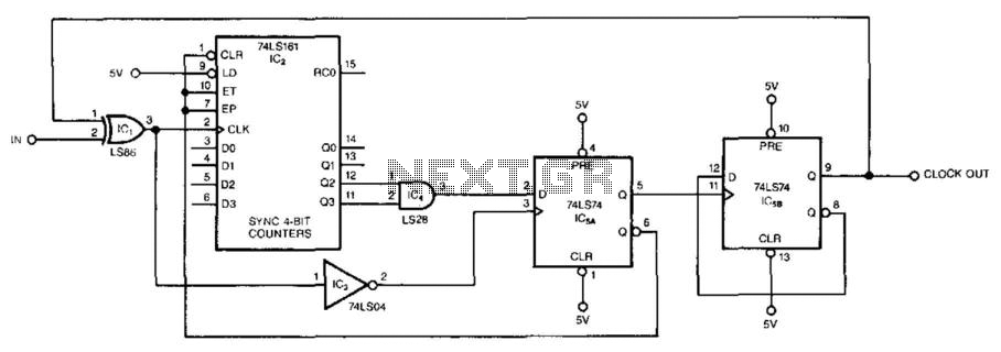
This circuit symmetrically divides an input by virtually any odd number. The circuit contains n + 1 clocks to achieve the desired divisor. By selecting the proper n, which is the decoded output of the 74LS161 counter, divisors from...