
Windshield wiper control

The interval wiper circuit provides an efficient way to manage the operation of windshield wipers, allowing them to operate intermittently rather than continuously. The circuit typically involves a timer IC, such as the NE555, configured in astable mode to generate a pulse-width modulation signal. The two connections to the car's wiper control allow the circuit to interface directly with the existing wiper motor control system.
The ground connection is essential for establishing a common reference point for the circuit. The use of a potentiometer (500 K) in conjunction with a fixed resistor (100 K) enables the user to adjust the interval timing of the wipers. By varying the resistance, the timing can be tailored to suit different weather conditions or personal preferences.
In practical implementation, the circuit may include additional components such as diodes for protection against back EMF generated by the wiper motor, as well as capacitors to stabilize the power supply and filter out noise. The choice of components should be made with consideration of the specific vehicle's electrical characteristics to ensure compatibility and reliability.
Overall, this circuit design offers a straightforward solution for enhancing windshield wiper functionality, providing drivers with improved visibility during adverse weather conditions.Here"s a good way to set windshield wipers on an interval circuit. Only two connections to the car"s wiper control, plus ground, are required Variable control can be accomplished by substituting a 500 K pot in series with a 100 K fixed resistor in place of the 560 K.
Related Circuits
Loop stability analysis typically begins with an open-loop Bode plot of the system being examined, such as the power stage of a buck or flyback converter. This plot allows the designer to extract phase and gain information within the...

A voltage-controlled oscillator (VCO) operates similarly to a voltage-to-frequency converter (VFC). Its output frequency is determined by a control voltage input. In the circuit diagram, 'd' represents the amplifier input voltage, which is set to 0.6V, while 'h' denotes...
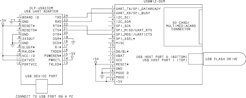
USB flash drives offer a convenient method for storing various types of information in a compact form. Also referred to as thumb drives and USB keys, these drives are well-suited for applications in data loggers and other projects based...
Interest is expressed in constructing a solid-state control system for a Warn 8274 self-recovery winch. The existing control method employs four constant-duty 200 amp solenoids. Two are switched in parallel to connect the field 1 terminal on the motor...
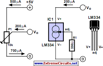
The adjustment control for the contrast of an LC-Display typically utilizes a 10-kilohm potentiometer. This arrangement functions adequately, provided that the power supply voltage remains constant. However, in situations where the power supply is variable, such as with a...
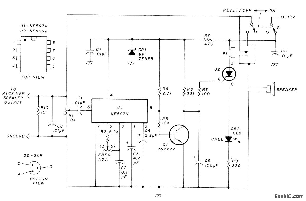
This circuit allows for monitoring a local VHF FM repeater for calls from friends without the need to listen to the background chatter or noise from the repeater. Its operation mimics that of Motorola paging units, where a special...