
Sp6691 Remote Control 100khz Infrared Led Driver

Loop stability analysis is a critical aspect of control system design, particularly in power electronics. The open-loop Bode plot serves as a foundational tool for assessing the frequency response of the system. By analyzing the gain and phase characteristics, designers can determine the stability margins and performance metrics of the converter under consideration. The selection of an appropriate compensator structure is essential to achieve the desired crossover frequency and phase margin, which directly influences the transient response and steady-state behavior of the converter.
The total loop gain analysis is a vital step in ensuring system stability. It requires careful placement of poles and zeros in the compensator design to maintain stability when the feedback loop is closed. In systems with multiple feedback paths, such as those employing the TL431, the designer must consider the interactions between different feedback loops. The TL431 is a versatile voltage reference and error amplifier that can be configured in various ways to achieve desired performance characteristics. The type-2 configuration, as depicted in the schematic, provides a means to enhance phase margin and improve transient response by utilizing both fast and slow feedback paths.
In applications where weighted feedback is implemented, the complexity of the analysis increases. The interaction between the different feedback paths can lead to intricate dynamics that must be carefully managed to avoid instability. The exploration of these dynamics in the context of power converters is essential for advancing the design of robust and efficient power supply systems. The insights gained from analyzing the TL431 in a multiple-loop configuration can inform best practices for designing converters that require precise control and stability across a range of operating conditions.Loop stability analysis usually starts from an open-loop Bode plot of the plant under study, e. g. the power stage of a buck or a flyback converter. From this diagram, the designer CAN extract phase and gain data within the frequency range of interest. His job then consists in identifying a compensator structure which will lead to the selected cros sover frequency affected by the right phase margin. The final step requires the study of the total loop gain, the power plant followed by the compensator, showing that the poles/zeros placed on the compensator ensure stability once the loop is closed. If this operation is rather straightforward with single loops, the operation becomes more complicated with converters implementing weighted feedback.
This paper capitalizes on the Ref. [1] work and explores different ways to apply the technique to power converters featuring multiple feedback paths. The TL431 a Multiple Loop System The TL431 alone, CAN be modeled as a multiple loop feedback system. Figure 1 shows a TL431 classically wired in a type-2 configuration, as described in Ref. [2]. From this schematic, one CAN identify so-called slow and fast lanes. Figure 20. Schematic of the Two-switch Forward Power Supply featuring a Weighted Feedback with TL431 🔗 External reference
Related Circuits
This infrared (IR) remote extender enhances the range of most basic IR remotes operating at a 40KHz modulation frequency significantly. When in operation, the remote is aimed at the detector on the circuit, and a button is pressed. The...
This circuit uses three easily available 555 timer ICs. All three work as astable multivibrators. The first 555 has an on period and off period equal to 1 sec. This IC controls the on/ off periods of the other...
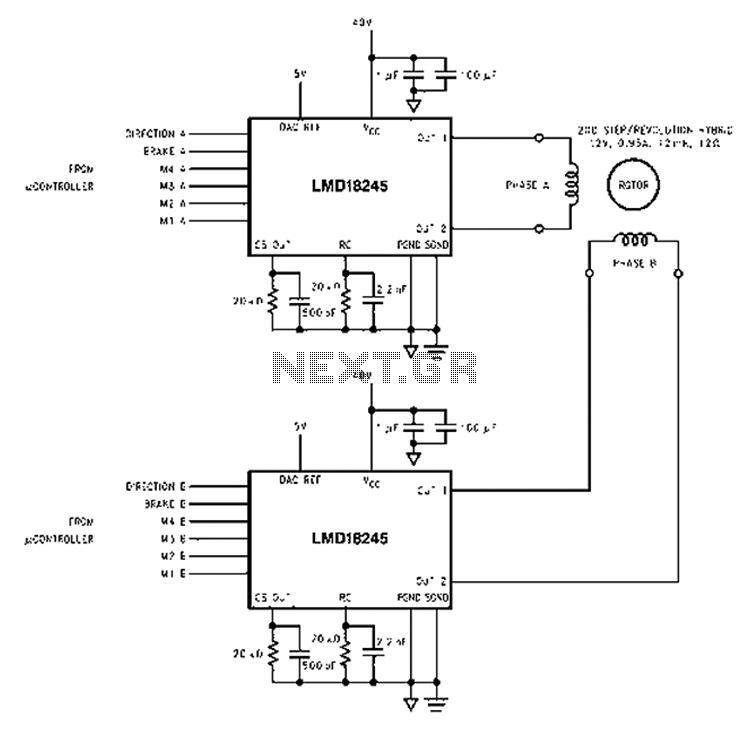
An innovative current detection method eliminates the power loss associated with the sense resistor in series with the motor. A 4-digit analog converter (DAC) facilitates digital control of the motor current path, simplifying the implementation of full, half, and...
Examine a traditional Hartley oscillator circuit, and you'll note its trademark: a tapped inductor that determines the frequency of oscillation and provides oscillation-sustaining feedback. Although you can easily calculate the total inductance required for a given frequency, finding the...
This circuit is designed to serve as a programmable LED display for various applications. It features an 8 x 32 LED dot matrix interfaced with a Xino (or Arduino). In addition to the display, the circuit includes two buttons...
Logic power control of an analog regulator can be useful in applications where a digital circuit or controller needs to manage a power source, such as in EEPROM. In electronic systems, managing power effectively is crucial for the performance and...