
Windshield wiper hesitation control unit

The 555 timer in astable mode operates by continuously switching between its high and low states, generating a square wave output. In this configuration, the timing cycle is defined by the resistors and capacitor connected to the timer. The formula for calculating the frequency (f) of the oscillation is given by:
\[ f = \frac{1.44}{(R1 + 2R2) \cdot C1} \]
Where:
- R1 is the resistor connected between the discharge pin (pin 7) and Vcc.
- R2 is the resistor connected from the threshold pin (pin 6) to the discharge pin (pin 7).
- C1 is the timing capacitor connected between the threshold pin (pin 6) and ground.
The duty cycle, which determines the proportion of time the output is high versus low, is influenced by R2 and R3, particularly the potentiometer used for adjustment. When the potentiometer is varied, it changes the resistance in the circuit, thereby altering the timing intervals. The minimum time delay, when R3 is at zero ohms, is established by R2, ensuring that the circuit operates within the desired timing range.
In practical applications, this circuit can be employed in various timing and delay scenarios, such as in light flashers, timer circuits, and sound generators. The ability to adjust the timing with a potentiometer provides flexibility for different requirements, making this circuit versatile in electronic designs. Proper selection of the capacitor and resistor values is essential for achieving the desired oscillation frequency and duty cycle.This circuit uses the 555 timer in the asta-ble or oscillatory mode. The length of time the timer is off is a function of the values of CI, R2, and R3. The potentiometer which controls the amount of "hesitation" (Approximately 2 to 15 seconds) R2 provides a minimum time delay when R3 is at its zero ohms position.
Related Circuits
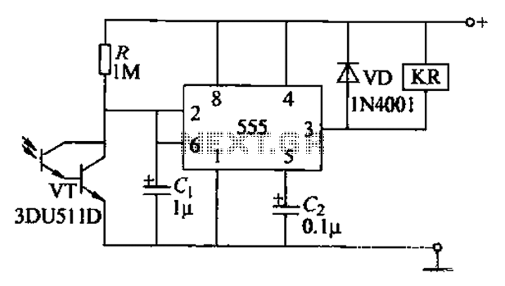
The circuit utilizes a Darlington-type phototransistor as the sensing element, which enhances sensitivity to low light levels, making it suitable for detecting reflected light signals. When the Darlington phototransistor is exposed to light, its resistance decreases, causing the voltage...
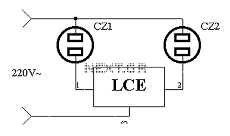
The application circuit operates the device as illustrated below. It is designed for cooling electrical equipment, typically utilizing a cooling fan to dissipate heat. The LCE employs a synchronous control socket on the device and its connections remain unchanged....
Here a simple design for an attractive tone. They operate on a passive principle, ie without amplification. The circuit only weakened and therefore require no power. As can be seen, the circuit is built with two T-filters in the...
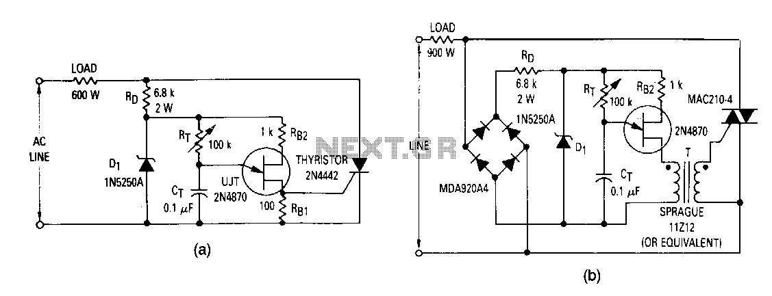
The most elementary application is a half-wave control circuit. The thyristor is acting both as a power control device and as a rectifier, providing variable power to the load during the positive half cycle and no power to the...
R2 47Ω 1/4W Resistor, D1 LED (any dimension, shape, and color), Q1 Infrared Photo Transistor (any inexpensive type), Q2 BC327 45V 800mA PNP Transistor, SW1 SPST Toggle or Slide Switch (optional, see note), B1 3V Battery (2 x 1.5V...
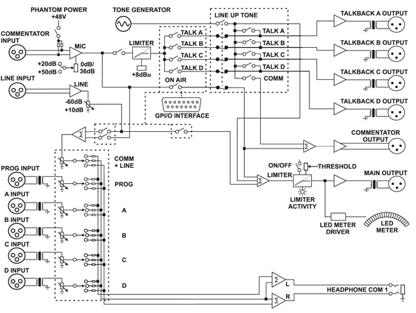
The unit offers a comprehensive commentator position with a line-level input. It features an individual commentator output and an additional output that combines commentator and line input audio. A limit indicator on the main panel signals when the adjustable...