
Audio tone control circuit

This circuit design implements a passive tone control system utilizing two T-filters to adjust bass and treble frequencies without amplification. The absence of active components means that the circuit does not require an external power source, making it suitable for low-power applications, such as small amplifiers, particularly those with a power rating around 250 mW.
The circuit operates on a line-level signal, ensuring compatibility with standard audio sources. The two T-filters are configured similarly to those found in active tone control circuits, but in this design, the output of the second filter is connected to ground instead of an operational amplifier. This configuration results in a passive attenuation of the audio signal.
The components involved in this circuit include resistors and capacitors, which determine the frequency response and the extent of bass and treble adjustment. The resistors R1 and R3 are both valued at 10 kΩ, while R2 is set at 1 kΩ. The potentiometers P1 and P2, each rated at 100 kΩ, allow for user adjustment of the bass and treble levels, respectively.
Capacitors C1 and C4 are both 10 nF, providing the necessary coupling for the T-filter configuration. C2, with a value of 100 nF, further shapes the frequency response, while C3, at 1 nF, fine-tunes the treble adjustment. The circuit also includes C5, a 10 µF capacitor, which may serve as a coupling capacitor or for DC blocking, ensuring that only AC signals pass through.
In summary, this passive tone control circuit is a straightforward and effective solution for adjusting audio frequencies in low-power applications, providing a simple method for enhancing audio performance without the complexity of active components.Here a simple design for an attractive tone. They operate on a passive principle, ie without amplification. The circuit only weakened and therefore require no power. As can be seen, the circuit is built with two T-filters in the same way as the active bass / treble tone control. Only is the right of the two filters are not at the output of an opamp, but mass. P1 and P2 adjusts the bass to the treble. To hear more bass, you need to P1 in the direction of rotation R1. Contrast to more high tones, you must P2 in the direction of rotation C3. Of course this is not a HiFi sound system, but it is best for small amps like the 250 mW amplifier. Note that the circuit operates at line-levels, they must to get the amp! Parts List R1, R3 = 10kW R2 = 1 kOhm P1, P2 = 100 kOhm C1, C4 = 10 nF C2 = 100 nF C3 = 1 nF C5 = 10 uF 🔗 External reference
Related Circuits
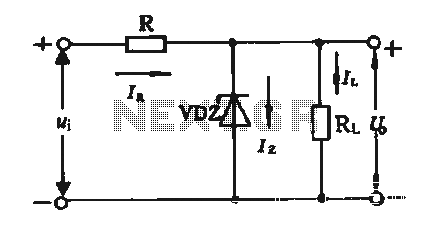
The simple voltage regulator circuit consists of a silicon regulator and a resistor. It is designed to rectify and filter DC voltage, as illustrated in the accompanying figure. The voltage regulator is connected in parallel with the load, and...
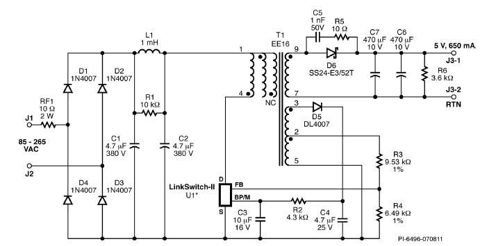
A simple 3.25W constant voltage/constant current (CV/CC) charger can be designed using the LinKSwitch family IC manufactured by Power Integrations. This electronic circuit project is intended to provide a 5-volt output with a maximum current of 650mA. The 3.25W...
The electronic fishing shrimp machine circuit consists of an astable oscillator, an inverter circuit, and a high-voltage output circuit, as depicted in Figure 20. The astable oscillator circuit includes a time-base integrated circuit (IC), resistors R3 and R4, a...
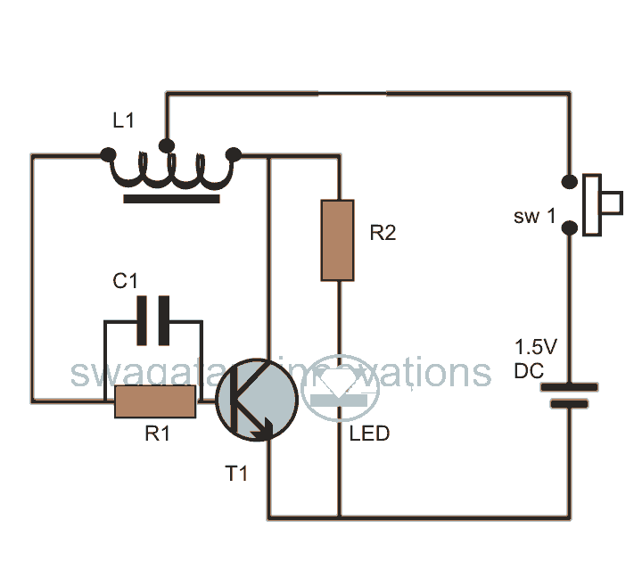
This post discusses blue and white LED drivers utilizing a joule thief circuit. Further exploration of the circuit's functionality is provided, along with simulation points. The joule thief circuit is a simple and efficient boost converter that allows for the...

A simple touch dimmer circuit diagram using the TT6061 IC, which is a touch control integrated circuit used for light dimmer circuits and lamp dimmer circuits. The touch dimmer circuit utilizing the TT6061 IC is designed to provide a user-friendly...
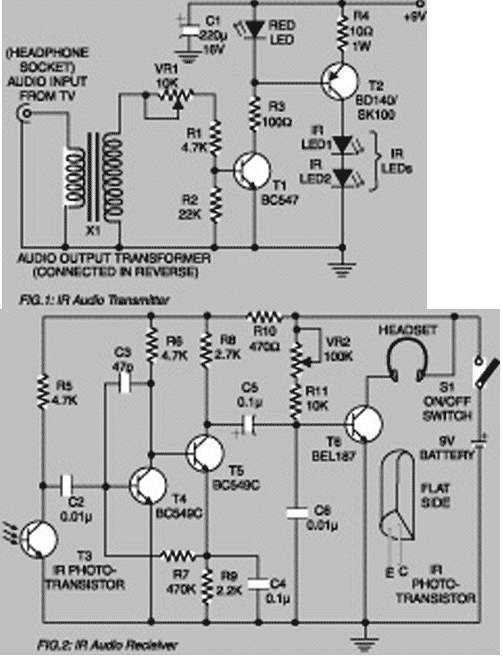
Using this low-cost project one can reproduce audio from TV without disturbing others. It does not use any wire connection between TV and headphones. In place of a pair of wires, it uses invisible infrared light to transmit audio...