
Wiper speed controller

The described circuit utilizes a relay to manage the power distribution to the wiper motor, facilitating its operation in a controlled manner. The timer circuit plays a crucial role in this setup, generating periodic signals that actuate the relay. When the relay is energized, it closes the contacts, allowing current to flow to the wiper motor, thus initiating its movement.
Potentiometer R1 is integrated into the circuit to adjust the pulse rate, which determines how frequently the wiper motor operates. By varying the resistance of R1, the time interval between each activation of the motor can be modified, allowing for customization based on environmental conditions such as rain intensity.
Potentiometer R5, on the other hand, is responsible for controlling the pulse width. This adjustment influences the duration for which the wiper motor remains active during each cycle. A longer pulse width will result in extended wiper operation, while a shorter pulse width will decrease the active time.
It is essential to calibrate both potentiometers after installation in a vehicle to ensure optimal wiper performance. This adjustment allows the user to tailor the wiper's operation to specific needs, enhancing visibility and safety during inclement weather. Proper tuning of these parameters contributes significantly to the efficiency and effectiveness of the wiper system.
The overall design emphasizes user control and adaptability, making it suitable for various driving conditions. The relay, timer circuit, and adjustable potentiometers work in harmony to provide a reliable and efficient wiper motor operation.The relay which applies power to the wiper motor is actuated at periodic intervals by the timer circuit, closing the wiper motor contacts. Potentiometer R1 serves as the pulse rate control and potentiometer R5 as the pulse width control. These two controls should be adjusted for optimum performance after the unit is installed in a car.
Related Circuits
This is a circuit to use a standard, low quality opto isolator to transfer an analogue signal with reasonable linearity and without complicated feedback loops to monitor and linearise it. The circuit was designed to interface a mains driven...
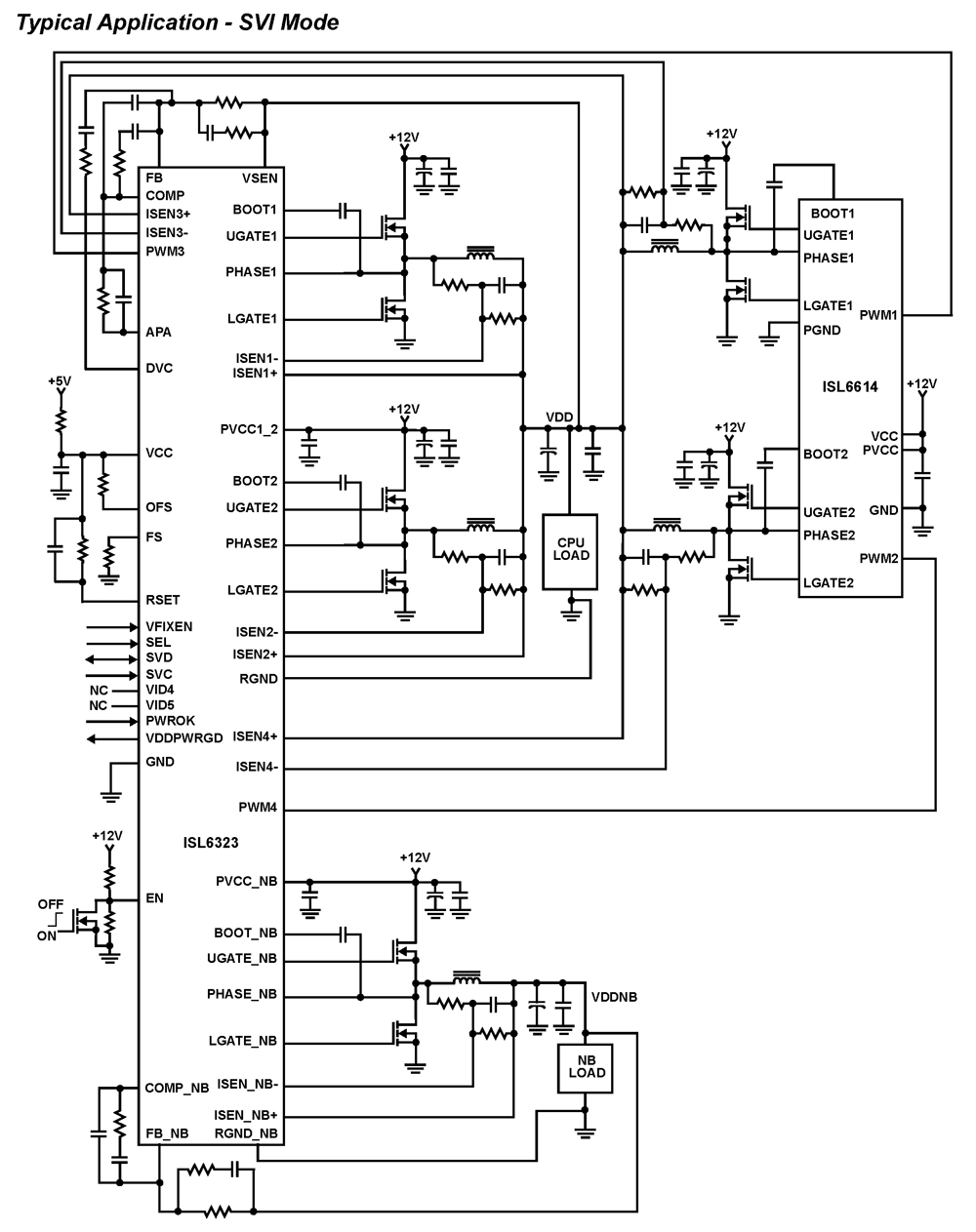
The ISL6323 dual PWM controller provides high efficiency and precise regulation through two synchronous buck DC/DC converters. It supports hybrid power control for AMD processors, operating via either a 6-bit parallel VID interface (PVI) or a serial VID interface...
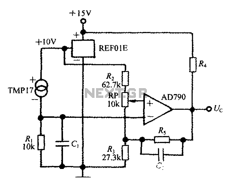
An adjustable thermostat controller circuit is widely used in everyday applications, such as for maintaining a constant temperature in soldering irons. The circuit utilizes the TMP17 sensor along with the REF01E voltage reference to ensure a stable 10V supply...
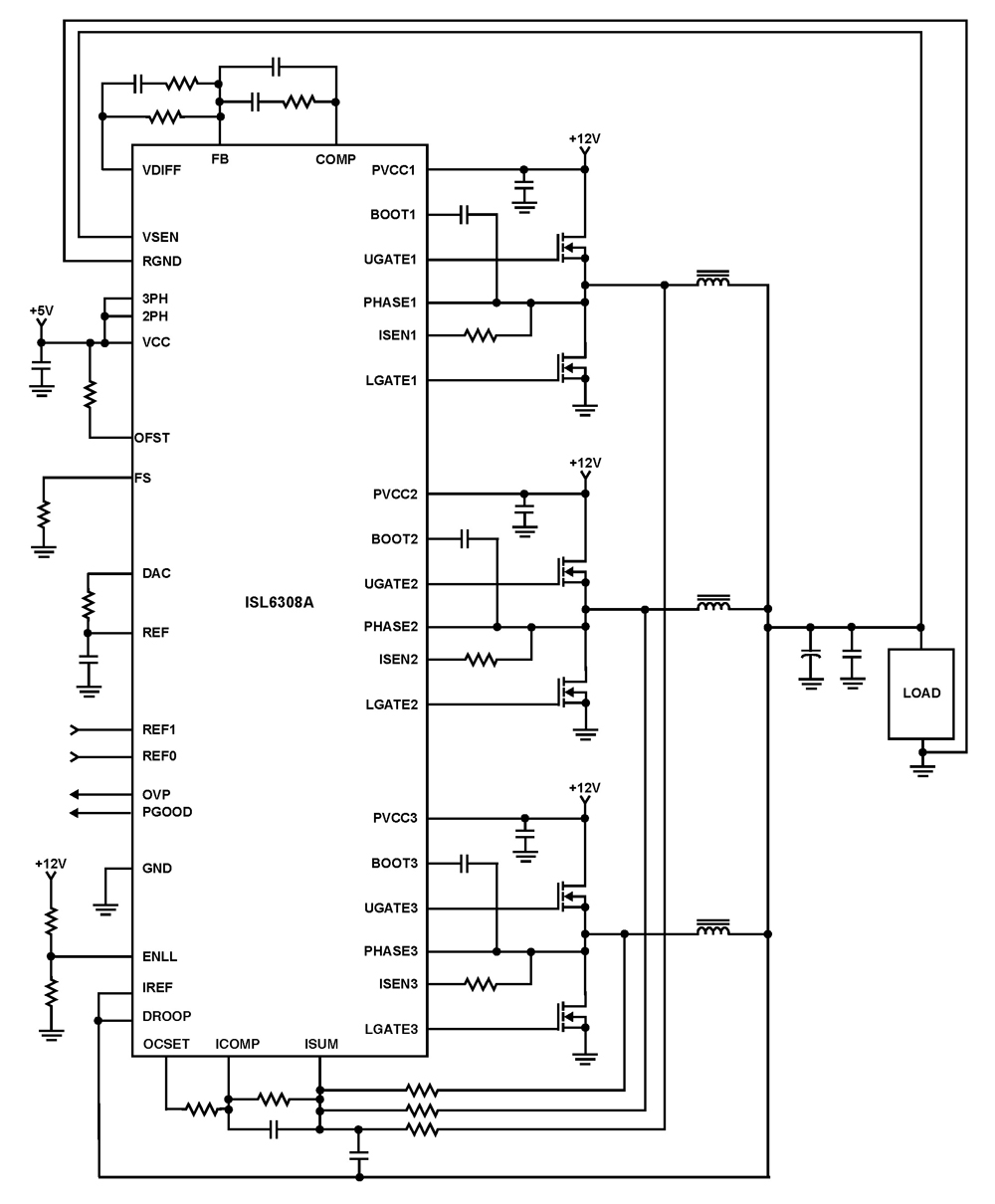
The ISL6308A is a three-phase PWM control integrated circuit (IC) equipped with built-in MOSFET drivers. It delivers precise voltage regulation suitable for various applications, including high current low voltage point-of-load converters, embedded systems, and other general low voltage medium...
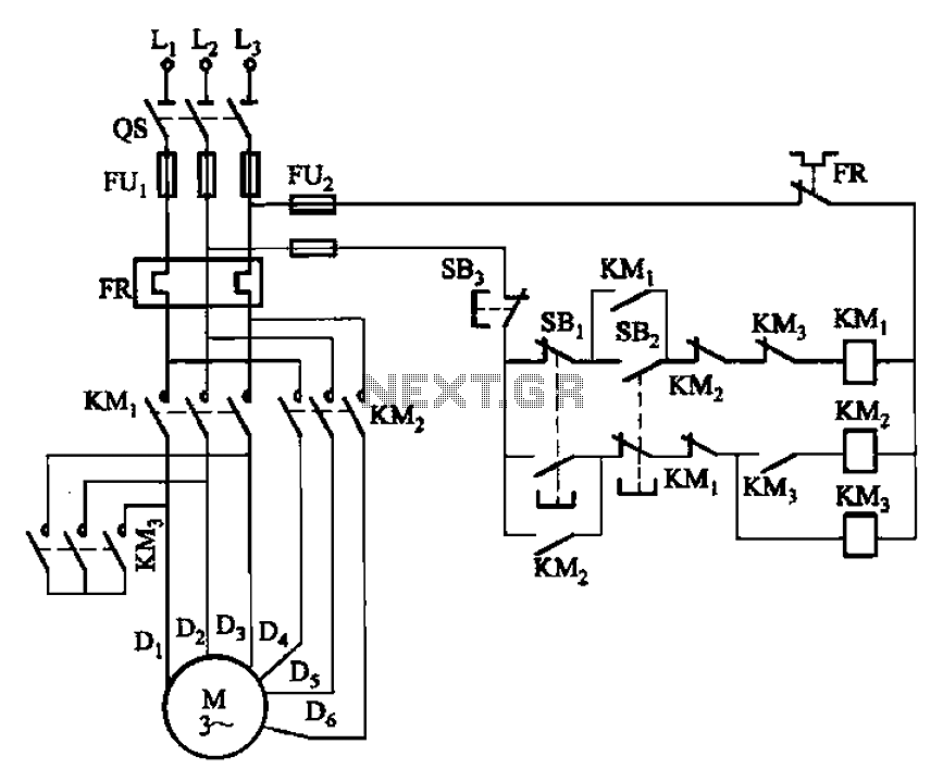
The circuit depicted in Figure 3-96 features a low-speed operation button (SBz), a high-speed operation button (SBi), and a stop button (SB3). In this configuration, a motor is connected in such a way that when the low-speed button is...
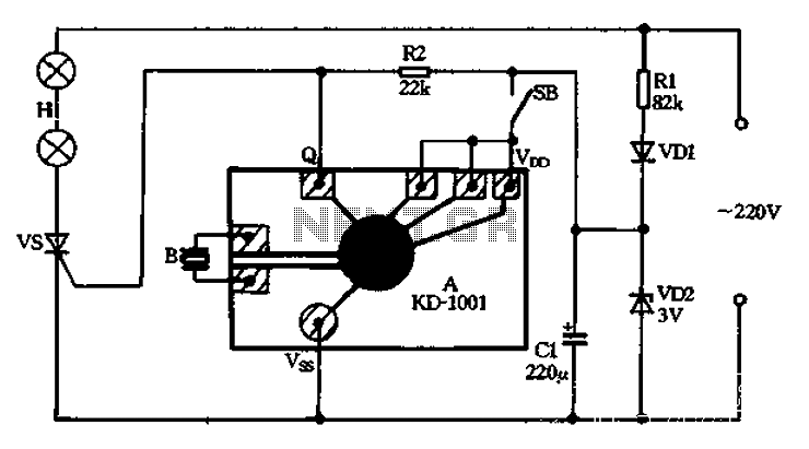
A 220V AC power supply is utilized through a resistor R1 to step down the voltage, followed by a rectifier VD1 and a filter capacitor C1, resulting in an output voltage of approximately 3V DC for the KD-1001 manifold....