
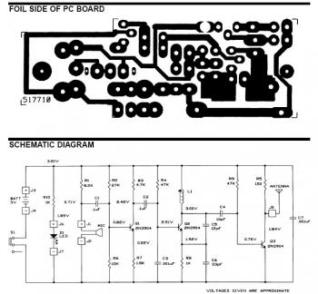
Wire Tracer (Transmitter)
")
The circuit utilizes a 556 timer IC, which consists of two 555 timers in a single package. This configuration allows for efficient modulation of the output signal. The first timer (IC1b) generates a continuous square wave signal, while the second timer (IC1a) modulates this signal to create a frequency shift between 2100 Hz and 2200 Hz. This frequency shift is critical for distinguishing the signal from background noise and other electrical signals that may be present in the environment.
Resistor R6 plays a pivotal role in the circuit by connecting to a short wire antenna, which facilitates the transmission of the modulated signal. The length of the antenna is optimized for the frequency range being used, ensuring effective transmission and reception. The ground connection is essential for stabilizing the circuit and providing a reference point for the signal.
When the antenna is placed near a cable, the inductive coupling allows the signal to be picked up by the receiver, which is designed to demodulate and amplify the incoming signal. This enables the user to trace the path of the wiring or identify breaks in the conductor without direct contact with live wires, enhancing safety during troubleshooting.
Overall, this circuit exemplifies a practical solution for wire tracing applications, leveraging well-established electronic components and principles to achieve reliable performance in identifying electrical wiring configurations. The schematic for the receiver complements this transmitter circuit, providing a complete solution for electrical diagnostics.The circuit depicted here forms one half of a device that will prove extremely handy when tracing the path of electrical wiring in a building or to locate a break in a wire. The system is based on similar equipment that is used by technicians in telephone exchanges. The operation is straightforward. You require a generator that delivers an easily recognizable signal which, using a short antenna, is inductively coupled to a simple, but high gain, receiver. To create a useful transmitter it would suffice to build a simple generator based on a 555. But as the adjacent diagram shows, a 556 was selected instead. The second timer (IC1a) is used to modulate the tone produced by IC1b. The output frequency alternates between about 2100 Hz and 2200 Hz. This is a very distinctive test signal that is easily distinguished from any other signals that may be present.
Resistor R6 is connected to a piece of wire, about ten centimeters long, that functions as the antenna. The ground connection (junction C2-C3) is connected to ground. When the antenna is connected directly to a cable, it is possible to determine at the other end of the cable, with the aid of the receiver, which conductor is which (don`t do this with live conductors!).
The schematic for the matching receiver may be found elsewhere in this website. 🔗 External reference
Related Circuits
The frequency range for the FM broadcast band is 90 MHz (megahertz, or 90 million cycles per second). An FM microphone utilizes a variable tuned circuit, allowing it to be adjusted to a quiet frequency within the local FM...
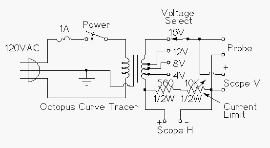
This project involves constructing a low-cost curve tracer suitable for testing a wide variety of electronic components both in-circuit and out of circuit. It is easy to construct and extremely useful for identifying defective parts, especially semiconductors, in electronic...
Two detector systems in the Hall-A spectrometers utilize potentially flammable gases: the Vertical Drift Chambers (VDC) and the Focal Plane Polarimeter (FPP) straw tubes. This document aims to provide a user manual for the gas supply system and fulfill...
The rewiring of an entire house is underway following a significant malfunction of two antique knob and tube circuits. A challenge has arisen with the outdoor lighting setup, specifically concerning a detached garage that features a porch light above...
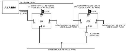
The following circuit illustrates the Ford Probe Single Wire Door Alarm System. This Single Door Locking Wire manages both LOCK and UNLOCK functions, indicating that the pulse wires must be connected to the same vehicle wire. The system primarily...
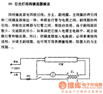
The four-wire ballast connection of a fluorescent lamp consists of four lead wires, which include main and auxiliary coils. The connection of the two lead wires in the main coil is similar to that of a second-line ballast; both...