
octopus curve tracer

The curve tracer circuit operates by generating a sine wave voltage that is applied to the electronic component under test. This voltage is modulated to provide a dynamic representation of the component's characteristics as it responds to varying current levels. The output from the device is fed to an oscilloscope, which is configured to display the current-voltage relationship in an X-Y format.
The step-down transformer is a critical component of the circuit, providing the necessary voltage levels while ensuring safety through the inclusion of a fuse. The voltage select switch allows the user to choose between different voltage levels, enabling the testing of components with varying operating voltages. The current limit variable resistor is essential for protecting sensitive components by setting a maximum current threshold during testing.
The oscilloscope's response to the test probes is indicative of the component's health. A vertical line on the oscilloscope indicates an open circuit, while a horizontal line indicates a short circuit. As the sine wave is applied, the resulting trace on the oscilloscope provides a visual representation of the component's impedance characteristics, allowing for the identification of faulty components based on the shape and behavior of the trace.
The physical construction of the octopus within the utility box is designed for both functionality and accessibility. The use of an aluminum plate for mounting the controls enhances durability and provides a secure interface for user interaction. The RG-58 coaxial cables ensure minimal signal loss and maintain high fidelity in the measurements taken.
Overall, this low-cost curve tracer serves as a versatile tool for electronics enthusiasts and professionals alike, facilitating the identification and analysis of various electronic components with ease and precision.This project involves the construction of a low-cost curve tracer that is suitable for testing a wide variety of electronic components both in-circuit and out of circuit. It is easy to construct and extremely useful for finding defective parts, especially semiconductors, in electronic devices.
The octopus is used in conjuction with an oscilloscope set to display in X-Y mode. It displays voltage across the test probes on one axis and current through the probes on the other axis. A scope with both Horizontal and Vertical inputs (X-Y mode) is required. This is my version of a circuit that has been around since at least the 1960s, I added the ability to select voltage taps on the filament transformer and adjust the amount of current through the probes.
Power is applied to the step-down transformer through a 1 amp fuse and a power switch. The transformer has output taps at 4V, 8V, 12V and 16V. If you can`t find an equivalent transformer, a more common 6V/12V transformer will work. The voltage select switch allows one of four voltages to be selected. The current limit variable resistor selects the maximum current through the test probes. When the probes are open, the scope will display a vertical line, when the scope probes are shorted, the scope will display a horizontal line. The octopus places a constantly changing sine wave voltage across the probed device. The horizontal axis shows the current through the probes and the vertical axis shows the voltage across the probes.
As the sine wave changes, the scope trace loops around in accordance with the associated current and voltage readings from the probe. Probing different electronic components will produce a variety of unique scope patterns. The octopus was built into a deep 4"x4" electrical utility box, as shown in the photo. A tall lid was used for the top to make enough room for the transformer. The box knock-outs on the front were removed and the switches and potentiometer were mounted on an aluminum plate that was screwed into the side of the utility box.
The test jack holes were drilled directly into the box and the power and oscilloscope cables were secured to the box with common Romex cable clamps. The oscilloscope cables were made with flexible RG-58 coax pieces and terminated with BNC connectors for direct connection to the scope.
Connect the Horizontal and Vertical connectors to the oscilloscope inputs, power up the octopus and adjust the scope`s vertical and horizontal amplifiers for full screen-width lines when the probes are open and shorted. The octopus is especially good at finding defective semiconductor devices. Power transistors often short out when they fail. The octopus can quickly find shorted parts, even in circuit. Leaky transistors and diodes will have curves with rounded corners instead of right angles. Keep in mind that antique germanium transistors tend to show as leaky, even when they are perfectly good devices.
By placing the probes on a transistor`s emitter and collector leads, then touching the base lead with your finger, you can observe the device`s gain by seeing how much the curve changes. In-circuit testing with the octopus is a bit of an acquired skill, a wide variety of curves can be found and faulty components can be identified.
If suspicious components are found, they can be removed from the circuit and tested further. 🔗 External reference
Related Circuits
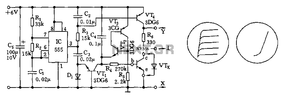
The transistor characteristic curve tracer circuit depicted in Figure 555 illustrates the characteristics of a transistor. It utilizes two voltages: a step wave applied to the base (b) to generate different base currents (Ib), and a sawtooth waveform at...

The tracer detects the weak magnetic field of any current-carrying house wiring and amplifies this signal to a level that is adequate for driving a magnetic earpiece. The unit uses a telephone pick-up coil to detect the magnetic field. The...

Suitable for matching diodes or examining the VI characteristics of two-terminal devices (such as diodes), this circuit is designed for laboratory use. Resistors R1 and R2 can be increased in value, and a higher voltage transformer can be utilized...
This simple circuit generates narrow pulses at about 700-800Hz frequency. The pulses, containing harmonics up to the MHz region, can be injected into audio or radio-frequency stages of amplifiers, receivers and the like for testing purposes. A high-pitched tone...

This unit utilizes a dual trace oscilloscope with X-Y functionality as a display to test and demonstrate the operation of circuits and components such as transistors, diodes, zener diodes, and both terminated and unterminated transformers. A low-frequency sine wave...

Carefully examine the following circuit diagram and attempt to construct the circuit on a breadboard first. If it functions correctly, proceed to create its PCB version. The circuit diagram serves as a blueprint for constructing an electronic circuit on a...