
Wireless alarm FM transmitter module
The described alarm system circuit is designed to provide a customizable solution for security applications, allowing users to tailor the functionality and frequency of each unit. The foundational elements include a time delay mechanism, which is critical for preventing false alarms during user access periods. The use of a CD4001 quad NAND gate IC facilitates the logic operations necessary for triggering the alarm condition and controlling the oscillator function. The oscillator's frequency can be adjusted to create distinct alarm tones for each unit, enhancing the system's versatility.
The opto-isolator (TIL112) serves a dual purpose: it provides electrical isolation between the high-power transmitter and the low-power control circuit, while also enabling the control of the transmitter's power state. The choice of a 9V battery for the power supply ensures adequate voltage for the components while maintaining portability.
The design allows for the integration of various transmitter and receiver modules, including modern RF communication devices that can further enhance the system's range and reliability. The adjustable components, such as the variable capacitor and resistors, provide flexibility for tuning and optimizing the performance of the alarm system in various environments.
In summary, this circuit design offers a robust foundation for creating a personalized alarm system, utilizing readily available electronic components while allowing for scalability and customization based on user requirements.There are a lot of alarm systems on the market but you might be inclined to build your own. This little project can be put together using inexpensive parts readily available. The alarm transmitter module allows for a delayed trigger and auto turn-off as it is designed assuming that once the remote alarm has been triggered it will remain on until i t is turned off manually. Looking at the circuit switch S1 can be a open contact switch, a magnetic switch or other normally open switch of your own choosing for the application you have in mind. As soon as S1 is closed there is a time delay determined by R1-C1. This provides an allowable reset time for exit and re-entry to deactivate the alarm with the " Reset button " before it is triggered by the CD4001 gates (C-D).
If there is no reset the gates (C-D) trigger Q1 and the tone generator (A-B) set -up as an oscillator ( the frequency of which is determined by R3/C3 ). Q1 turns on the Opto-isolator (TIL112) which powers the Transmitter module via a 9V battery. It will remain on for the duration of the oscillation being transmitted. After a delay determined by R2-C2 charging up to the positive DC rail gates (C-D) trigger will shut off the oscillator (A-B) and Q1 which in turn will turn off the supply to the transmitter via the opto-isolator reverting to the monitor mode where only a fraction of a miliamp is used from the battery in that mode.
You may decide to build several small alarm units after your success with the first one. One way of identifying each of these transmitters is assigning a different tone for each unit by changing the frequency. To do this R3 at points (A) as shown on the oscillator portion of the CD4001 (A-B) must be changed. While using a fixed capacitor C3 at point B an encoder could be substituted at A and B in series with C3 instead of the present fixed R3.
Such an encoder is shown made up with a 14 pin DIP for seven switches, actually, four would probably suffice using parallel switching for different chosen resistor values for each frequencies. On the other hand, if each transmitter would be assigned its own frequency with fixed R3/C3 this would simplify the construction and do just as well.
As for the transmitter I have used the Radio/TV FM transmitter in #3b and a small portable FM radio taking the signal from the headphones output for processing and it worked very well. The transmitter doesn`t need an antenna for close range and it tunes the lower FM band around 88mHz with the variable capacitor.
There are now many new types of miniature Tx/Rx modules that can be had from electronic suppliers that could be used and greatly simplify the project. The FM "Mini- receiver" on this page could be used, R1 (PC type) controls the regeneration and after adjusting for best reception it should be locked in place with a dab of silicon as you may need to readjust it later.
The 25pF variable capacitor tunes the selected frequency and R2 provides the load and must be adjusted for maximum output to an amplifier stage without distortion. Another option worth considering is the RF Detector described in Handy Dandy Little Circuit #15b. 🔗 External reference
Related Circuits
A typical low-cost FSK modulator, TA0038, is implemented by injecting the modulation voltage into the phase-locked loop (PLL) of the carrier synthesizer. This can be achieved in two ways: by summing the modulation voltage with the loop error voltage...
Long-distance infrared transmitter circuit diagram. This simple circuit offers a considerable range by utilizing three infrared transmitting LEDs (IR1 through IR3) in series to enhance the radiated power. To further improve directivity and power density, the IR LEDs can...
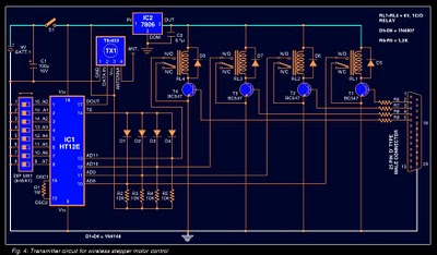
Stepper motors are widely used in applications such as process control, machine tools, and robotics. In particular, remote control of stepper motors is essential in robotics and process control. This document provides the circuit diagrams for both the transmitter...
In this project, you will make a simple low-power broadcast-type circuit, using a crystal oscillator integrated circuit and a collector modulated AM oscillator. You can connect the circuit to an amplified microphone (no amplified microphone has a too low...
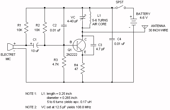
The electret microphone operates with a current of 200 µA, which varies by ±3 µA in response to sound waves. This variation results in a voltage of 2V across resistor R1 and 4V across the microphone. As sound waves...
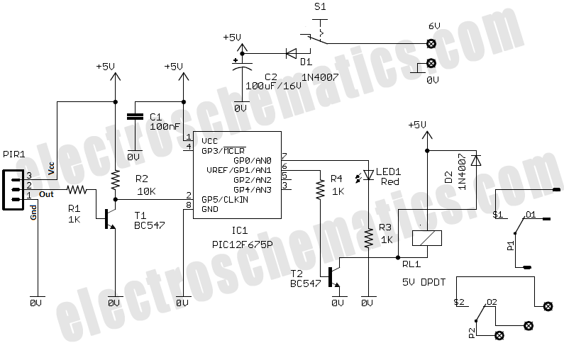
Crime in general is still on the rise, and having a security alarm installed is no longer a prerequisite of the wealthy. Here is a simple and compact security solution. A compact security alarm system can be designed to enhance...