
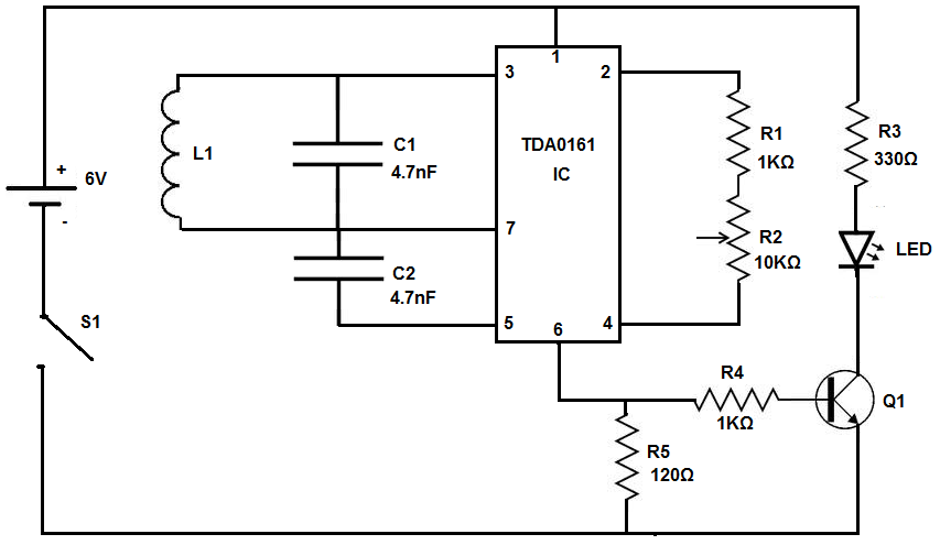
DTMF Proximity Detector

The DTMF-based IR proximity detector circuit operates on the principle of modulated infrared light transmission and reception. The core components involved include the DTMF generator and decoder, which work together to facilitate the identification of reflected IR signals. The DTMF generator IC1 generates specific audio frequencies corresponding to the DTMF tones, which are then converted into an infrared signal by IR LED1. The modulation of the IR light allows for the detection of objects that reflect the light back towards the photodetector, D1.
The circuit design incorporates several critical elements to ensure proper functionality. The use of a Darlington pair for amplification allows for sufficient current to drive the IR LED, ensuring adequate signal strength for detection. The variable resistor VR1 plays a crucial role in adjusting the intensity of the emitted IR light, thereby influencing the effective range of the proximity detection capability.
Additionally, the shielding of the photodetector is essential to prevent false readings due to direct IR light from the transmitter. This design consideration enhances the accuracy of the detection system by ensuring that only reflected IR light is registered by the photodetector.
The output from the DTMF decoder facilitates the integration of the proximity detector into broader applications, allowing for the connection to various devices or systems that can respond to the detection of an object. The versatility of this circuit makes it suitable for various applications, ranging from security systems to automation tasks, where proximity detection is essential. Overall, this DTMF-based IR proximity detector circuit exemplifies a practical application of telephony ICs in a sensor-based system.A DTMF-based IR transmitter and receiver pair can be used to realize a proximity detector. The circuit presented here enables you to detect any object capable of reflecting the IR beam and moving in front of the IR LED photo-detector pair up to a distance of about 12 cm from it. The circuit uses the commonly available telephony ICs such as dial-to ne generator 91214B/91215B (IC1) and DTMF decoder CM8870 (IC2) in conjunction with infrared LED (IR LED1), photodiode D1, and other components as shown in the figure. A properly regulated 5V DC power supply is required for operation of the circuit. The transmitter part is configured around dialer IC1. Its row 1 (pin 15) and column 1 (pin 12) get connected together via transistor T2 after a power-on delay (determined by capacitor C1 and resistors R1 and R16 in the base circuit of the transistor) to generate DTMF tone (combination of 697 Hz and 1209 Hz) corresponding to keypad digit 1 continuously.
LED 2 is used to indicate the tone output from IC3. This tone output is amplified by Darlington transistor pair of T3 and T4 to drive IR LED1 via variable resistor VR1 in series with fixed 10-ohm resistor R14. Thus IR LED1 produces tone-modulated IR light. Variable resistor VR1 controls the emission level to vary the transmission range. LED 3 indicates that transmission is taking place. A part of modulated IR light signal transmitted by IR LED1, after reflection from an object, falls on photodetector diode D1.
(The photodetector is to be shielded from direct IR light transmission path of IR LED1 by using any opaque partition so that it receives only the reflected IR light. ) On detection of the signal by photodetector, it is coupled to DTMF decoder IC2 through emitter-follower transistor T1.
When the valid tone pair is detected by the decoder, its StD pin 15 (shorted to TOE pin 10) goes high`. The detection of the object in proximity of IR transmitter-receiver combination is indicated by LED1.
The active-high logic output pulse (terminated at connector CON1, in the figure) can be used to switch on/off any device (such as a siren via a latch and relay driver) or it can be used to clock a counter, etc. This DTMF proximity detector finds applications in burglar alarms, object counter and tachometers, etc.
🔗 External reference
Related Circuits
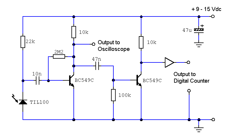
A circuit designed to extract and measure the modulated carrier of an infrared remote control. The circuit does not physically separate control pulses from modulation; instead, it amplifies the entire received signal, allowing the waveform to be ideally displayed...
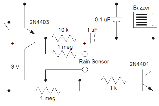
This rain detector provides immediate notification when it begins to rain, allowing time to close windows and secure belongings. Alternatively, a molded power supply with a simple voltage regulator can be employed to reduce the voltage to 3 volts....
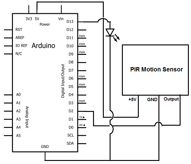
Once the motion sensor detects motion, the Arduino can be programmed to activate an LED, turn on a motor, sound a buzzer, etc. In this circuit, for simplicity, an LED will be turned on when the motion sensor detects...

This enhanced infrared detector is designed for use with commercial infrared remote control handsets. This compact circuit is effective for quick go/no-go applications. The infrared detector circuit is engineered to respond to signals emitted by infrared remote control devices, commonly...
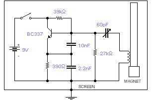
This basic oscillator will detect the Earth magnetic field. The ferrite rod and coil are taken from an old Medium Wave receiver and a small magnet is glued at one end. Tune to a medium wave commercial station until...
The device being constructed will serve as a metal detector, capable of locating metal objects such as coins, nails, and keys, including car keys that may be misplaced. It can also detect gold, although it may not possess industrial...