
Wireless Electronics for Communication

The oscilloscope measurements are critical in ensuring accuracy in the evaluation of the Driver and Buffer Amplifiers. The use of a 10:1 attenuation probe is essential to mitigate the effects of parasitic capacitance and input resistance, which can introduce significant errors in high-frequency applications such as those found in the NorCal 40A transmitter.
For Problem 1, the simulation and construction of the Driver Amplifier (Q6) involve a careful transient analysis to observe the amplifier's response at a frequency of 7 MHz. The objective is to configure the DC offset and input amplitude to match the expected output waveforms. This process requires meticulous attention to the emitter current, which must remain below 50 mA to prevent damage to the transistor and ensure reliable operation.
In Problem 2, the focus shifts to the Buffer Amplifier (Q5) and the associated 8V TX switch (Q4). The construction of these components is guided by the schematic provided, which highlights specific components required for assembly. The integration of capacitors (C36, C37, C38, C39), inductor (L6), and resistors (R10, R11) with the Buffer Amplifier is crucial for achieving the desired performance. Additionally, the inclusion of components for the 8V TX switch (C57, D11, Q4, R9, R24) must be executed with precision.
The removal of the previously soldered 1.5 kOhm resistor is a necessary step to ensure that the circuit functions correctly and that the RIT switch operates as intended. This highlights the importance of following assembly instructions meticulously to avoid any potential issues during the testing phase. Overall, the successful completion of these tasks will lead to a thorough understanding of the amplifier circuits within the NorCal 40A transmitter, contributing to enhanced performance and reliability.For all measurements with the oscilloscope, use the oscilloscope probe with the 10:1 attenuation to minimize measurement errors due to the capacitance of coaxial cable and the input resistance of the oscilloscope. Problem 1. The goal of this problem is to simulate, build and measure the Driver Amplifier (Q6) of the NorCal 40A transmitter.
We will closely follow Problems 21 and 22 in the book. The schematic of the Driver Amplifier is shown below with the parts used for this problem set highlighted (click on the schematic to enlarge it). Check also the NorCal 40A Assembly Manual for a complete schematic (last two pages of the manual). Run a transient analysis of the circuit for about 100 us with a sinusoidal input at 7 MHz. Adjust the dc offset and the amplitude of the sinusoidal input (representing the waveform generator) to obtain waveforms similar to the ones shown below.
Check that you do not exceed an emitter current of about 50 mA at the transistor. 1. c Solder the components for the Driver Amplifier onto the NorCal 40A board. Then perform the measurements and caculations described in parts A, B, and C of Problem 21 in the book. Problem 2. The goal of this problem is to build and measure the Buffer Amplifier (Q5) of the NorCal 40A transmitter.
We will closely follow Problem 23 in the book. The schematic of the Buffer Amplifier (Q5) and the 8V TX switch (Q4) is shown below with the parts used for this problem set highlighted (click on the schematic to enlarge it). Check also the NorCal 40A Assembly Manual for a complete schematic (last two pages of the manual). 2. b Solder the parts needed for the Buffer Amplifier (C36, C37, C38, C39, L6, Q5, R10, R11) and the 8V TX transistor switch (C57, D11, Q4, R9, R24) onto the NorCal 40A printed circuit board.
At this point you should also remove the 1. 5 kOhm resistor shown in the picture below that was soldered to he bottom side of the printed circuit board in Problem Set 8 to make the RIT switch operational before the 8V TX power line was available. 🔗 External reference
Related Circuits
This FM radio-controlled anti-theft system can be used with any device operating on a 6 to 12-volt DC power supply. The mini VHF FM transmitter is installed in the vehicle at night when it is parked in the driveway...
This project is a miniature, VHF FM (wideband) Wireless Microphone transmitter of the type that are commonly referred to as BUG's. Note that "BUGS" are illegal but "Wide-Band Frequency Modulation Wireless Microphones" (WBFMWMs) are not, as so many people...
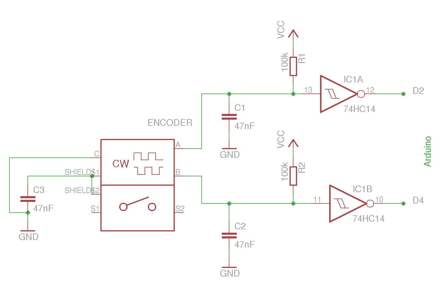
The example circuit and code should be sufficient to begin without delving into additional details. A rotary encoder is an electromechanical component with a shaft that records rotation and converts it into electrical pulses to indicate the direction of...
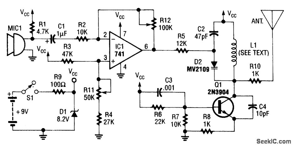
An operational amplifier integrated circuit (741) amplifies the audio signal from microphone 1 (MIC1), with resistor R12 determining its gain. The amplified audio signal is then directed to the oscillator circuit, which includes transistor Q1 and associated components. D2...
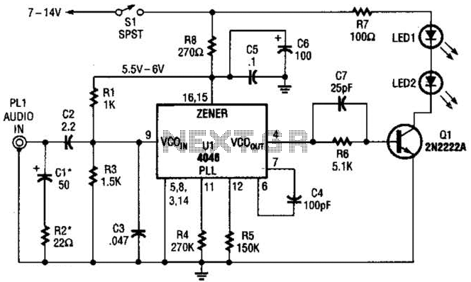
The transmitter for the wireless headphones is constructed using a CD4046 CMOS phase-locked loop, which is paired with a driver transistor and a set of infrared LEDs. While the CD4046 contains two phase comparators, a voltage-controlled oscillator (VCO), a...

Embedded systems serve as the core of most electronics-based systems, enabling data access, processing, storage, and control. While some simple electronic circuits can be designed without a microprocessor or microcontroller, this approach is often economically impractical, except for basic...