
wireless fm transmitter

The wireless transmitter circuit is designed for efficient operation in the VHF range, primarily targeting FM transmission applications. The use of the BF494 transistor as the oscillator allows for a stable and adjustable frequency output, which is essential for clear signal transmission. The integration of a varicap diode enables frequency modulation, enhancing the transmitter's capability to encode audio signals onto the carrier frequency effectively.
The output stage, utilizing the 2N3866 transistor, is critical for amplifying the weak signals generated by the oscillator stage. This Class A amplifier configuration is known for its linearity, providing a clean amplification of the signal. The specified output power of 200-250 milliwatts is suitable for short-range transmission, making the circuit ideal for personal or hobbyist applications.
Proper assembly and shielding are vital for optimal performance. Mounting the circuit on a high-quality substrate minimizes parasitic capacitance and inductance, which can adversely affect performance. The aluminum enclosure not only provides physical protection but also serves as an electromagnetic shield, reducing interference from external signals.
Potentiometers VR1 and VR2 allow for user adjustments, ensuring that the transmitter can be fine-tuned for specific applications or conditions. The recommendation to use a 12V rechargeable battery pack is practical, as it provides sufficient power while maintaining portability. The heat sink for transistor T2 is necessary to dissipate heat generated during operation, preventing thermal overload and ensuring reliability.
Finally, the caution against operating the transmitter without an antenna is crucial, as doing so can lead to damage from reflected power. The adjustment of trimmers VC1 and VC2 is essential for achieving the best performance, ensuring that the transmitter operates at peak efficiency. Setting the fundamental frequency near 100 MHz places the transmitter within a commonly used FM band, allowing for compatibility with standard FM receivers.The wireless transmitter ambit congenital about transistor T1 (BF494) is a basal low-power variable-frequency VHF oscillator. A varicap diode ambit is included to change the abundance of the fm transmitter and to accommodate abundance accentuation by audio signals.
The achievement of the oscillator is about 50 milliwatts. Transistor T2 (2N3866) fo rms a VHF-class A ability amplifier. It boosts the oscillator signals` ability four to bristles times. Thus, 200-250 milliwatts of ability is generated at the beneficiary of transistor T2. For bigger results, accumulate the ambit on a good-quality bottle adhesive lath and abode the transmitter central an aluminium case. Shield the oscillator date application an aluminium sheet. Potentiometer VR1 is acclimated to alter the axiological abundance admitting potentiometer VR2 is acclimated as ability control.
For hum-free operation, accomplish the wireless fm transmitter on a 12V rechargeable array backpack of 10 x 1. 2-volt Ni-Cd cells. Transistor T2 charge be army on a calefaction sink. Do not about-face on the transmitter after a analogous antenna. Adjust both trimmers (VC1 and VC2) for best manual power. Adjust potentiometer VR1 to set the axiological abundance abreast 100 MHz. 🔗 External reference
Related Circuits

AM Transmitter. It is illegal to operate a radio transmitter without a license in most countries. This circuit is deliberately limited in power output. An AM transmitter is designed to modulate an audio signal onto a carrier wave for the...

An output of 4 mA to 20 mA that is linearly proportional to the input voltage is provided by the current transmitter. Line rejection is included. The current transmitter operates within a specified range, providing an output current that is...
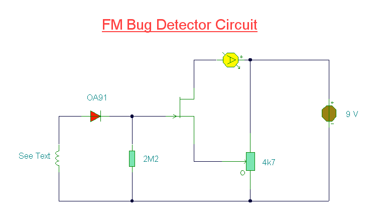
The site features several low-power transmitters, but until now, there has been no receiver. This circuit can be utilized to scan an area or room, indicating whether a surveillance device is active. The challenge in creating an effective detector...
This AM radio circuit is a low-power transmitter operating in the broadcast band. Its simplicity is achieved through the use of a single-transistor amplifier stage. The AM radio transmitter circuit operates within the standard AM broadcast band, typically ranging from...

Use of IR (infrared) light as a method for wireless communication has become popular for remote control applications. There are a number of different standards for such communication. In this application note, the widely used RC5 coding scheme from...

The circuit in Figure 1 meets these criteria and uses only three off-the-shelf ICs and a few passive components. Although dedicated to conditioning the low-level signal a strain-gauge bridge produces, the circuit can operate with almost any resistive transducer...