
Easy fades fade switching circuit 2

This circuit utilizes a straightforward design to achieve a dimming effect for lighting applications. The core components include a capacitor (C), resistors (R and R1), and transistors (VT1 and VT2). The circuit operates by leveraging the charging and discharging characteristics of the capacitor to control the brightness of the lamp (E).
When the circuit is powered, the capacitor begins to charge through resistor R, resulting in a gradual increase in voltage across the capacitor. This increase influences the base of transistor VT2, allowing it to turn on progressively. As VT2 conducts, it reduces the effective resistance presented by high-power transistor VT1, which is responsible for driving the lamp. The lamp (E) thus brightens smoothly as the voltage rises, providing a visually appealing fade-in effect.
Conversely, when the switch is turned to the off position, the capacitor begins discharging through resistor R. This discharge process allows the lamp to remain lit for a brief period, but the brightness diminishes gradually as the capacitor voltage drops. The time it takes for the lamp to extinguish completely depends on the values of the capacitor and resistor used in the circuit, which can be adjusted to achieve the desired fade-out duration.
The circuit's design is robust, with no specific requirements for the transistors or other components, allowing for flexibility in component selection. The high back pressure rating for resistor R1 is crucial to ensure reliable operation under varying load conditions. Overall, this gradual clear/fade switch circuit is an effective solution for applications requiring controlled lighting transitions.End a two-wire connection gradually clear/fade switch circuit when the circuit is relatively simple to install. Turn on the lights when needed, H properly switch S dial upward, positive supply via] 2V R. The capacitor (1 charge, the C voltage across gradually increased, so make VT2 gradually step guide Annals of people, high-power tube VT1 equivalent resistance decreased, lamp E gradually brighten the dark. When the C full charge the brightness of the lamp will no longer change when you turn off the lights of the store s dial downward, C.
charge Pan R; to VT2 discharge lamp can be maintained light, but dichotoma brightness gradually darken over time, when (- charge when basic is done and the lights went completely extinguished. v r1 should be high back pressure power NI, N transistors, other components, no special requirements.
Related Circuits
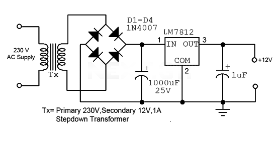
This is a straightforward 12V power supply circuit diagram. It features a fixed voltage output and is based on the LM7812 voltage regulator integrated circuit. The 12V power supply circuit utilizing the LM7812 voltage regulator is designed to provide a...
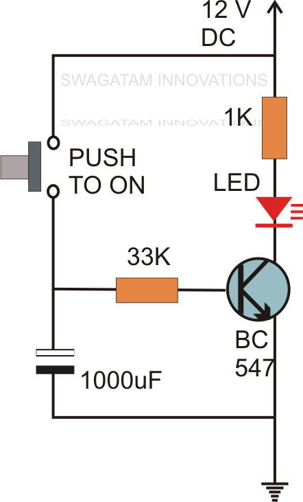
Without the specified delay, the circuit could malfunction or even sustain damage. A capacitor, which is a crucial component of the circuit, is positioned at the other end of the base resistor rather than directly connected to the base...

The automatic alarm circuit comprises a DTMF automatic dialing system, a password control circuit, a voice detection and alarm circuit, a telephone interface circuit, a power supply circuit, and a keyboard display circuit. The automatic dial-up alarm utilizes the...
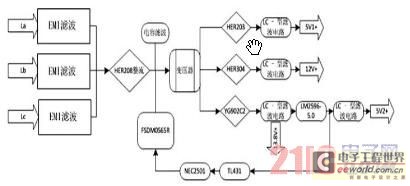
Currently, the switching power supply boasts high performance with an efficiency of 75%. The efficiency of single-scale integration switching power supplies has exceeded 90%. This advancement addresses energy concerns and enhances the performance of numerous energy-saving electrical devices. The...
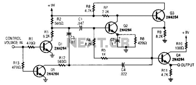
A DC control voltage varies the effective resistance in the feedback network consisting of capacitors C4, C3, C1 and resistors R12, R3. Additionally, Q2 and Q3 serve as the oscillator transistors. The circuit operates by utilizing a DC control voltage...
The circuit illustrated in Figure 3-127 utilizes a time relay (KT) in place of a speed relay. The timing duration is adjustable and typically set between 1 to 2 seconds. This circuit is designed to operate effectively in dusty...