
Wireless Switch

This non-contact control circuit is particularly advantageous for applications requiring hygiene or convenience, such as automatic hand dryers in public restrooms. The use of an infrared LED and phototransistor creates an effective sensing mechanism that minimizes wear and tear from mechanical switches. The operational amplifier (CA3140) serves not only to amplify the weak signal received from the phototransistor but also to provide a buffer that isolates the input from the output, enhancing the overall stability of the circuit.
The use of a voltage divider with the adjustable preset (VR1) permits fine-tuning of the sensitivity, allowing the circuit to be adapted to different environmental conditions or user preferences. The transistor BC548 acts as a switch, controlling the relay based on the amplified signal from the operational amplifier, ensuring that the appliance operates reliably.
The relay (RL1) is critical in this design as it provides the necessary isolation between the low-power control circuit and the high-power appliance, thus safeguarding the components from high voltages. The entire circuit can be housed in a compact enclosure, making it suitable for various installations. Proper alignment of the IR LED and phototransistor is essential for optimal performance, and any obstacles or misalignment can result in false triggering or failure to activate the appliance. This circuit exemplifies a modern approach to appliance control, leveraging infrared technology for enhanced user experience and operational efficiency.The circuit described here requires no physical contact for operating the appliance. You just need to move your hand between the infrared LED (IR LED1) and the photo transistor (T1). The infrared rays transmitted by IR LED1 is detected by the photo transistor to activate the circuit. This circuit is very stable and sensitive compared to other AC appliance control circuits. It is simple, compact and cheap. Current consumption is low in milliamperes. The circuit is built around an IC CA3140, IR LED1, photo transistor and other discrete components. When regulated 5V is connected to the circuit, IR LED1 emits infrared rays, which are received by photo transistor T1 if it is properly aligned. The collector of T1 is connected to non-inverting pin 3 of IC1. Inverting pin 2 of IC1 is connected to voltage-divider preset VR1. Using preset VR1 you can vary the reference voltage at pin 2, which also affects sensitivity of the photo transistor.
Op-amp IC1 amplifies the signal received from the photo transistor. Resistor R3 controls the base current of transistor BC548 (T2). The high output of IC1 at pin 6 drives transistor T2 to energise relay RL1 and switch on the appliance, say, hand dryer, through the relay contacts. The working of the circuit is simple. In order to switch on the appliance, you simply interrupt the infrared rays falling on the photo transistor through your hand.
During the interruption, the appliance remains on through the relay. When you remove your hand from the infrared beam, the appliance turns off through the relay. connect +5V supply to the circuit. 🔗 External reference
Related Circuits

The detector is a bit more complex. It amplifies a microphone and sends the resulting signal to an NE567 tone decoder. The amplifier is half of a 1458 opamp. The two 120K resistors attached to pin 3 keep the...
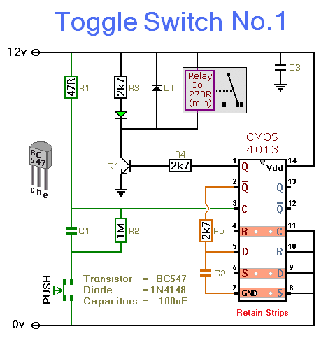
This simple circuit will energize and de-energize a relay with the push of a button. Pressing the button once will energize the relay, while pressing it a second time will de-energize the relay. The accompanying circuit provides a solid...

Designing a wide-range variable power supply using a linear regulator is straightforward; however, it suffers from poor efficiency when regulating a constant 60-volt source. A wide-range variable power supply can be implemented using a linear regulator, which allows for adjustable...
A simple whole house FM transmitter circuit diagram and description. Operating power is a 1.5V battery of any type. This circuit is able to transmit at a distance of 30 meters. The whole house FM transmitter circuit operates on a...
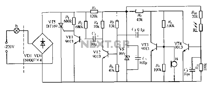
This circuit describes a sound and light control delay system for a walkway stairs light switch. It involves various components including 220V AC electric bulbs, diodes (VD1-VD4), and resistors. The circuit utilizes a rectifier regulator to stabilize the voltage...

A normally open pushbutton switch (SI) provides a positive input pulse to pin 4 of U1, activating the integrated circuit (IC). The output from U1 at pin 6 delivers base-drive current to a Darlington pair consisting of Q1 and...