
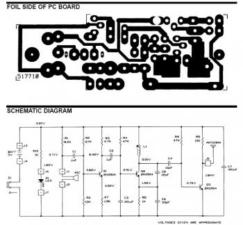
Wireless Telephone Line Spy

The phone bug circuit is designed to intercept and transmit audio signals from a telephone line to a nearby FM radio receiver. The primary function of this circuit is to allow for the wireless transmission of phone conversations, making it a valuable tool for surveillance purposes.
The circuit typically consists of several key components: a microphone, an amplifier, a modulator, and an FM transmitter. The microphone captures the audio signals from the phone conversation, converting sound waves into electrical signals. These signals are then amplified to ensure they are strong enough for transmission.
The modulator plays a crucial role by encoding the audio signals onto a carrier frequency suitable for FM transmission. This process involves varying the frequency of the carrier wave in accordance with the amplitude of the audio signal, which allows the information to be sent over the airwaves.
The FM transmitter then broadcasts the modulated signal, which can be received by any standard FM radio tuned to the appropriate frequency. The range of the transmission depends on the power of the transmitter and the sensitivity of the receiver. Proper circuit design must ensure minimal interference and optimal signal clarity to facilitate effective monitoring of conversations.
Power supply considerations are also critical in the design of this circuit. The circuit can be powered by batteries or an external power source, and it is essential to incorporate appropriate voltage regulators to ensure stable operation.
In summary, the phone bug circuit represents a sophisticated method of intercepting and transmitting telephone conversations wirelessly, leveraging FM technology for effective audio surveillance.This is a phone bug circuit. This wireless telephone line spy circuit can be used to transmit the phone conversation to a nearby FM radio. This circuit must.. 🔗 External reference
Related Circuits
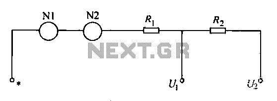
A voltmeter operates through a measuring mechanism in a specified circuit, utilizing a moving coil in series with additional resistance. The fixed coil is denoted as N1, while the moving coil is designated as N2. The additional resistances are...
It uses old pulse dial handsets and replaces the AC bell set with a 9 volt DC buzzer. The whole circuit runs from a 12 volt regulated DC supply and is suitable for short term battery operation (eg: Gel...
The frequency range for the FM broadcast band is 90 MHz (megahertz, or 90 million cycles per second). An FM microphone utilizes a variable tuned circuit, allowing it to be adjusted to a quiet frequency within the local FM...
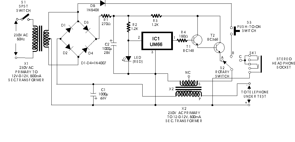
A circuit for an offline telephone tester that does not require a telephone line for testing a telephone instrument. The circuit is simple enough to be assembled by a novice with minimal electronics knowledge. A telephone line can be...
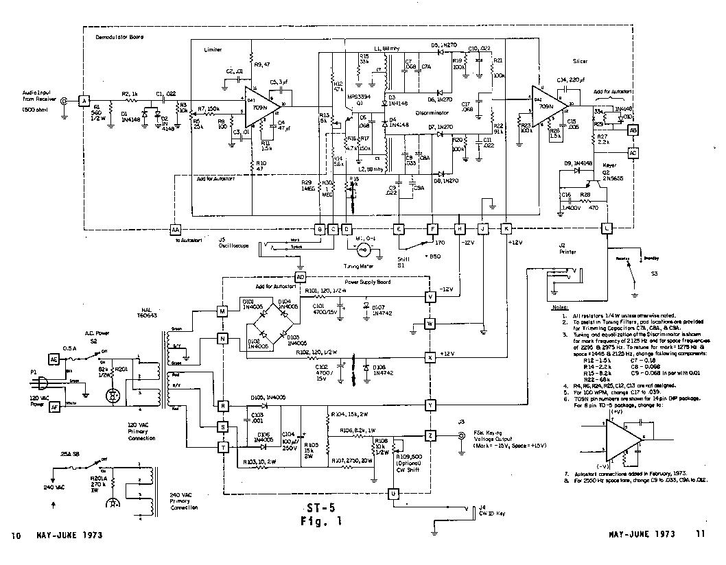
The Mainline ST-5 was introduced in the RTTY Journal in May 1970 and has quickly become a popular demodulator for RTTY. Due to the unavailability of back issues, the original article is being reprinted. Those interested in 100 baud...
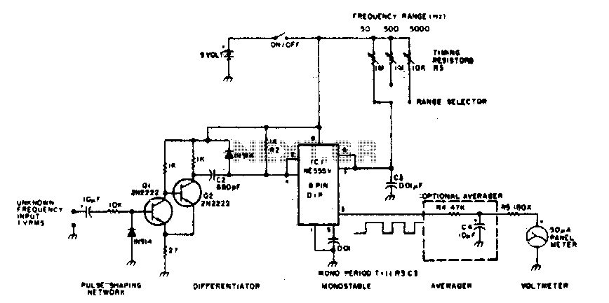
The 555 timer is utilized in a monostable multivibrator circuit that generates a pulse of fixed time width, which is activated by an unknown input frequency. The 555 timer in a monostable configuration operates by producing a single output pulse...