
Table circuit voltage electric lines

The voltmeter described functions by integrating a moving coil mechanism within a circuit, allowing for precise voltage measurements. The fixed coil (N1) and the moving coil (N2) are configured in series with additional resistances (R1 and R2) to optimize the measurement range and accuracy. The additional resistance plays a crucial role in defining the current flowing through the moving coil, represented by the equation I = U / R, where U is the root mean square (RMS) voltage being measured.
The relationship between the deflection angle (a) of the voltmeter's pointer and the measured voltage is governed by the equation a = KU / R2, where K is a constant that relates to the design of the voltmeter. The pointer's deflection is not linear with respect to the voltage due to the square relationship, which necessitates a non-linear scale for accurate readings across a range of voltages.
This voltmeter is capable of measuring both direct current (DC) and alternating current (AC) voltages. It can accurately gauge sinusoidal AC voltages, as well as non-sinusoidal AC voltages, ensuring versatility in various applications. The design considerations include ensuring that the additional resistance is appropriately selected to accommodate the inductive properties of the coils, thus maintaining measurement integrity across different voltage levels. The voltmeter's construction requires careful calibration to ensure that the scale reflects the non-linear nature of the voltage-to-deflection relationship, allowing users to interpret readings accurately.Voltmeter by the measuring mechanism in a given circle and moving coil in series to configure certain additional resistance. Nl is constant circle, N2 for the moving coil, R., Rz is additional resistance, U1, U2 to limit the amount of voltage.
When the additional resistance R is greater than the fixed and movable solid inductance coil, the coil is fixed and moving coil current effective value I = U / R wherein U- RMS measured voltage; additional resistance Nepal a voltmeter. Voltmeter deflection angle using the formula a = KU / Rz obtained, visible, proportional to the square pointer deflection angle and the measured RMS voltage, so the scale is not uniform indexing.
Similarly, the electric line voltage meter can measure the DC voltage and AC voltage sinusoidal and non-sinusoidal AC voltage has a valid value. .
Related Circuits
As a cyclist, there is a constant search for methods to enhance visibility during nighttime rides. The concept of the `NITE-RIDER` was developed to create a distinctive and attention-grabbing rear light for bicycles. This design features nine extra-bright LEDs...
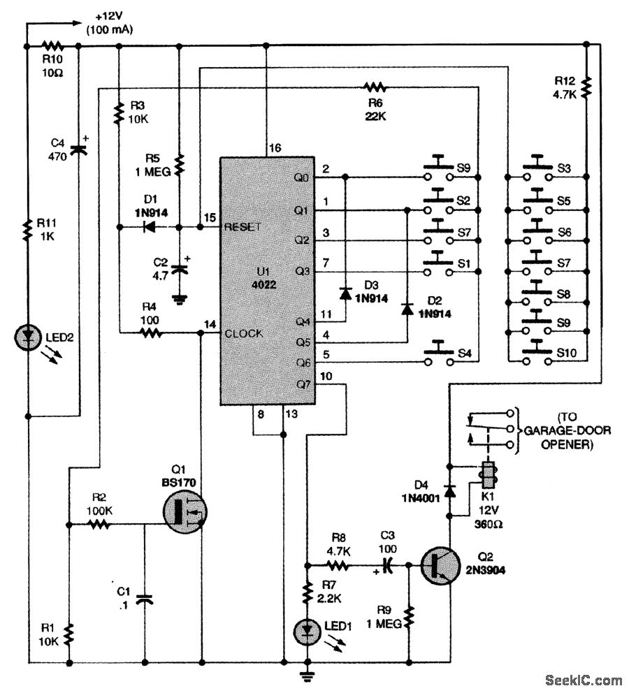
This circuit relies on the input of a correct sequence code. An incorrect number that is not part of the code triggers a reset of the circuit. When the correct code is entered, Q2 activates relay K1 for a...
Figure 1 illustrates an AND gate logic circuit with the logic expression P=A. Figure B depicts two photodiodes connected in series. When the input logic levels A=1 and B=1, the output P=1. Similarly, this configuration can be used to...
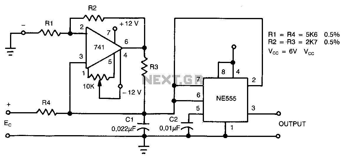
This circuit can accept positive, negative, or differential control voltages. The output frequency is zero when the control voltage is zero. The 741 operational amplifier forms a current source controlled by the voltage Ec to charge the timing capacitor...
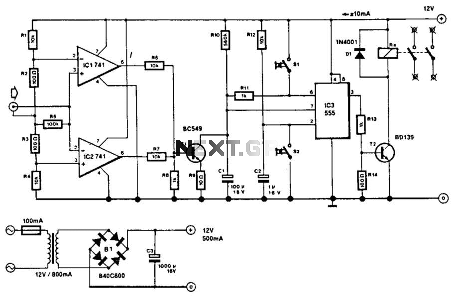
This circuit will disconnect the line supply to audio or video equipment if there has been no input signal for approximately 2 seconds. Switch SI provides manual operation, while switch S2 functions as a reset mechanism. This circuit allows...
The timer is utilized in a conventional setup, with the exception that the timing resistor has been substituted with a current source derived from the operational amplifier DA1 (741). This modification enables the achievement of excellent linearity, exceeding 3%....