
Wiring Diagram and Electrical Circuit Troubleshooting Of 1997 Chevrolet Blazer

The wiring diagram for the 1997 Chevrolet Blazer serves as a crucial reference for diagnosing and troubleshooting electrical issues within the vehicle's systems. The schematic provides a visual representation of the electrical connections and components, facilitating the identification of faults within the wiring harnesses, connectors, and electronic modules.
Key components depicted in the diagram include the battery, alternator, starter motor, and various fuses that protect the electrical circuits. The diagram also outlines the connections for the engine control module (ECM), which manages engine operations and communicates with other electronic systems, such as the transmission control module (TCM) for the four-speed automatic gearbox.
Furthermore, the schematic illustrates the wiring for the power accessories, including the power windows, door locks, and mirrors, which are typically controlled by switches located on the driver's door panel. The air conditioning system is also represented, highlighting the connections between the compressor, condenser, and the climate control module.
The anti-lock braking system (ABS) is another critical feature represented in the wiring diagram. It includes sensors that monitor wheel speed, ensuring optimal braking performance and safety. The dual airbags are connected through a dedicated circuit to the airbag control module, which is responsible for deploying the airbags in the event of a collision.
This comprehensive wiring diagram not only aids in troubleshooting electrical problems but also provides a valuable resource for modifications and repairs, ensuring that technicians can maintain the functionality and safety of the 1997 Chevrolet Blazer.The following circuit shows about Wiring Diagram and Electrical Circuit Troubleshooting Of 1997 Chevrolet Blazer. Features: powered by a 4. 3-liter Vortec V-6 engine, AM-FM stereo radio with CD, rear wheels moved through a four-speed automatic gearbox, air conditioner, 4, 400 rpm/250 lb-ft Power windows, power door locks, power mirrors, cruise contr
ol, dual air bags, anti-lock braking, producing 190 hp. [ freepdfmanual. com ] 🔗 External reference
Related Circuits
An alternative approach to utilizing operational amplifiers (op-amps) for power supply regulation is presented. This method necessitates an additional winding on the power transformer to provide the op-amps with a bipolar voltage of +/- 8 volts. The negative voltage...
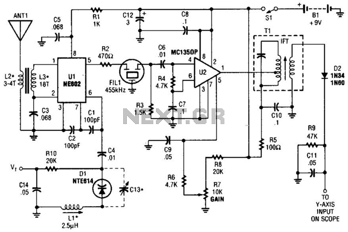
This circuit is designed for monitoring an amateur band or a specific segment of the radio spectrum. It utilizes an NE602 mixer-oscillator chip to generate a 455-kHz intermediate frequency (IF) signal. This signal is amplified by U2 and subsequently...
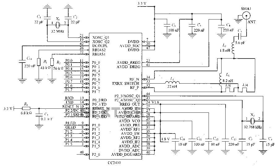
Figure C1 and C2 depict a 22 pF capacitor connected to a 32 MHz crystal oscillator circuit, which utilizes a quartz crystal for standard operation. Capacitors C3 and C4, each rated at 15 pF, are connected to a 32.768...
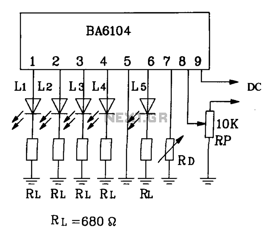
BA6104 is a five-digit LED level meter driver integrated circuit (IC) that features a basic application circuit. The input stage employs a PNP transistor with a composite base input, resulting in high input impedance. The output stage is configured...
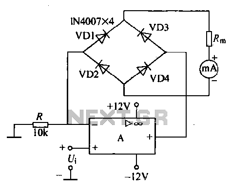
An operational amplifier, a diode bridge rectifier, and DC mA AC voltmeter tables are illustrated in the figure. The operational amplifier used is the LM324. The measured AC voltage is applied to the inverting terminal of the operational amplifier,...
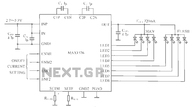
The MAX1516 charge pump drives up to 8 white LEDs with constant current regulation to achieve uniform light intensity, capable of delivering up to 30mA per LED for backlighting. The flash group LEDs (LED5 to LED8) are individually controlled,...