
Wiring diagram for 3 way switch

This circuit operates by sampling the audio signal from the speaker outputs of an audio amplifier. The audio signal is fed into a rectifier circuit, which converts the AC signal into a corresponding DC voltage that represents the audio volume level. This DC voltage is then used to control the brightness of the LEDs.
To implement this, a bridge rectifier can be used to ensure that the signal is always positive, regardless of the audio waveform's polarity. Following the rectification, a low-pass filter may be employed to smooth out the fluctuations in the audio signal, providing a stable voltage that corresponds to the average volume level.
The variable resistor (10k ohm VR) serves as an adjustable gain control, allowing the user to calibrate the sensitivity of the circuit to the audio input. This adjustment is crucial to ensure that the LEDs respond appropriately to the volume levels, preventing them from being overly dim or excessively bright.
For the LED configuration, a series of LEDs can be arranged in parallel, each connected to the output of the rectifier and filter circuit. The number of LEDs illuminated can correspond to the volume level, with more LEDs lighting up as the audio signal increases. Different colors can be used to create a visually appealing display, enhancing the overall experience.
To ensure proper functionality, it is important to consider the current-limiting resistors for each LED to prevent damage due to excessive current. The selection of these resistors will depend on the forward voltage of the LEDs and the supply voltage used in the circuit.
In summary, this project combines audio signal processing with visual display technology, allowing for an engaging interaction between sound and light. The design is straightforward, making it accessible for hobbyists and electronic enthusiasts looking to enhance their audio experiences visually.I like to see lights move to music. This project will indicate the volume level of the audio going to your speakers by lighting up LEDS. The LEDS can be any color so mix them up and really make it look good. The input of the circuit is connected to the speaker output of your audio amplifier. You want to build two identical units to indicate both right and left channels. The input signal level is adjusted by the 10k ohm VR. 🔗 External reference
Related Circuits
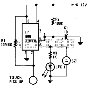
The circuit is based on a 555 oscillator (U1), which activates when a trigger is applied by touching the touch terminal connected to pin 2 of U1. Once triggered, LED1 and BZ1 (a piezoelectric buzzer) illuminate for a duration...
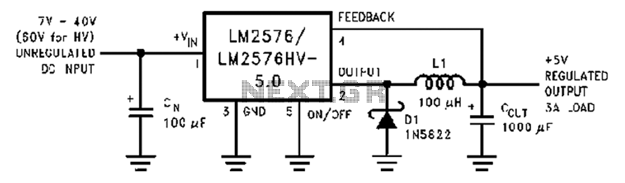
A wide range of 7 to 40V DC-DC step-down circuit that converts input voltage to 5V. This circuit operates as a buck converter, designed to efficiently reduce a higher DC voltage (ranging from 7V to 40V) to a stable output...
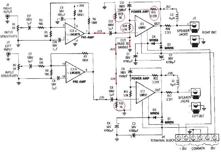
The LM12 audio amplifier circuit is designed to deliver high output power for loads with impedances of 4 ohms or 8 ohms. The maximum output power achievable by this amplifier is approximately 60 watts for a 4-ohm load and...
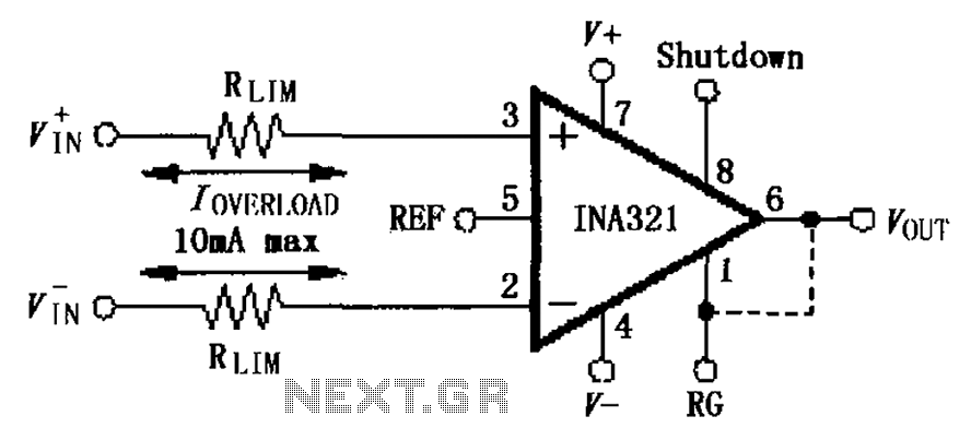
The input current protection circuit for the INA321/322 is illustrated. The INA321/322 features input terminal electrostatic discharge (ESD) protection diodes that become conductive when the input voltage exceeds the supply voltage by 500mV. The protection diodes will conduct, and...
The figure illustrates a digital display pressure measuring circuit diagram. The circuit operates with an additional voltage of approximately 12.8V and draws a current of 30mA. Under maximum gain conditions, the input voltage range is 0.8mV. The zero adjustment...
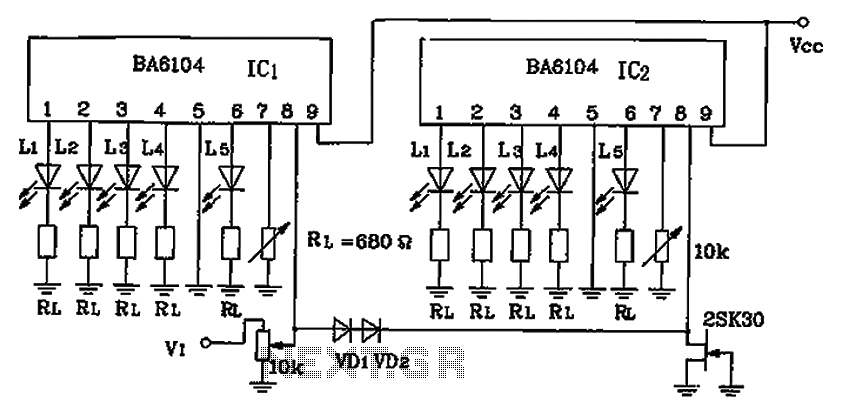
BA6104 is a five-digit LED level meter that functions as an LED display driver integrated circuit (IC). The configuration of the circuit is illustrated in the accompanying figure. The circuit utilizes a 10 by two-dot LED level display. The...