
Wiring Diagram for a Back-And-Forth Robot

The Clare IXDI404PI chip is a dual-channel, high-speed, high-current driver designed for driving inductive loads such as motors. In the context of a Back-And-Forth robot, this chip plays a crucial role in controlling the movement and direction of the robot's motors, enabling it to move forward and backward in response to control signals.
The schematic typically includes the following components and connections:
1. **Power Supply**: The IXDI404PI requires a stable power supply, often in the range of 4.5V to 15V. Proper decoupling capacitors should be placed close to the power pins of the chip to filter out noise and stabilize the voltage.
2. **Input Control Signals**: The chip accepts input signals from a microcontroller or other control circuitry. These signals determine the operation of the motor drivers. The input pins are typically connected to the output pins of a microcontroller, which can be programmed to send high or low signals based on the desired movement of the robot.
3. **Motor Connections**: The output pins of the IXDI404PI are connected to the motors. Each channel can drive a motor, allowing for independent control of two motors, which is essential for achieving forward and backward movement. The schematic should clearly depict the connection of each motor's terminals to the respective output pins of the chip.
4. **Protection Diodes**: To protect the IXDI404PI from back EMF generated when the motors are turned off, flyback diodes are often included in the schematic. These diodes are connected in parallel with the motors and serve to safely dissipate voltage spikes.
5. **Ground Connections**: A common ground should be established for the power supply, the IXDI404PI, and the microcontroller to ensure that all components operate correctly and to minimize potential differences that could lead to erratic behavior.
6. **Additional Components**: Depending on the design, additional components such as resistors, capacitors, and possibly additional logic gates may be included to condition the input signals or to provide feedback for more sophisticated control schemes.
The schematic serves as a vital reference for assembling the Back-And-Forth robot, ensuring that all connections are made correctly to facilitate reliable operation of the motors through the IXDI404PI chip. Proper layout and routing of the connections are critical for minimizing interference and ensuring the longevity of the components involved.A schematic that details the connections to the Clare IXDI404PI chip that is both the brains and the brawn of the Back-And-Forth robot that you can make yourself.. 🔗 External reference
Related Circuits
Electronic Schematic Circuit Diagrams Manual PDF Download. The document provides a comprehensive manual that focuses on electronic schematic circuit diagrams. These diagrams are essential tools for understanding and designing electronic circuits, offering visual representations of circuit components and their interconnections....

To enable a line-following robot to identify the line, it is essential to first detect the line itself. Several methods can be employed to distinguish a black line on a white background, or vice versa. One effective approach is...
The circuit diagram illustrates a five-use tri-state audio logic pen utilizing components such as the CD4066 and a 555 timer. The primary elements include a multivibrator, a four-way switch (CD4066, designated as IC1), and a gate circuit formed by...
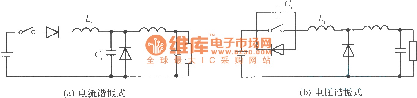
In a commonly used switching stabilized voltage supply, a resonant switch can be utilized to replace the shape of a step-down converter, resulting in a resonant converter circuit. The diagram illustrates the transformation from a step-down converter to a...
This is a sequence timer diagram composed of an NE555 timer. The timer can be set to any duration when the power is connected, allowing it to control an external system. In the circuit, K1-K3 are relays used to...
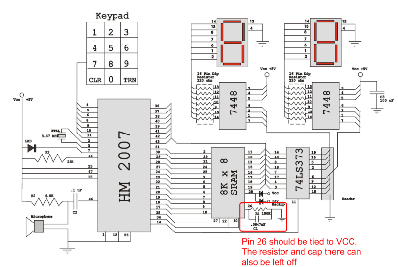
Verify the pin configurations on the datasheets for the integrated circuits used in your project, making necessary adjustments. In this instance, the RAM chip utilized had a non-inverted enable signal on pin 26, while the schematic assumed it was...