
Working Principle Television (TV)

The TV receiver circuit operates by first capturing the broadcast signal through an antenna, which is then processed by the tuner. The tuner selects the desired channel, filtering out other frequencies, and converts the selected signal to an intermediate frequency (IF). This IF signal is then amplified by the IF amplifier, which boosts the signal strength to a usable level. The AGC circuit plays a crucial role in managing fluctuations in signal strength, ensuring that the output remains stable despite variations in received signal quality.
Following amplification, the composite video signal is extracted, which contains both the luminance and chrominance information necessary for image display. The sound signal is also processed in parallel, where the FM demodulator retrieves the audio information from the modulated carrier. The synchronization circuits ensure that the video and audio signals remain in sync, providing a coherent viewing experience.
The vertical and horizontal deflection circuits are responsible for controlling the electron beam in cathode-ray tube (CRT) displays or the pixel arrangement in modern LCD and LED screens. These circuits dictate the scanning process, which reconstructs the image line by line on the screen.
The power supply circuit is essential for providing the necessary voltages to various components within the TV receiver. It includes voltage regulators and filtering capacitors to maintain stable operation and minimize noise. The careful design of the power supply ensures that all parts of the circuit receive the correct voltage levels needed for optimal performance.
In summary, the function of a TV receiver involves a complex interplay of various circuits and components, each serving a specific purpose in the process of capturing, processing, and displaying audio-visual content. The integration of these systems is critical for delivering a high-quality viewing experience.Before we study the working principles of a TV receiver, it is worth knowing a little about the journey of the object image that we usually see on TV. Images that we see is the production of a camera. The object image captured camera lens will be separated into 3 primary colors of red (Red), green (Green) and blue (Blue).
Results will be emitted b y the TV transmitter (Transmitter) in the form cromynance signal, luminance signal and syncronisasi. Besides pictures, television transmitters also carry voice signals are transmitted along with the picture signal. Images transmitted by the system of amplitude modulation (AM), while the sound with a system of frequency modulation (FM).
Both systems are used to avoid the noise (noise) and interference. The group assigned to the transmission frequency signal is called channel (channel). Each has a 6 MHz channel in one field frequencies (bands) are allocated to commercial television broadcasters, namely: This circuit consists of booster high frequency (HF amplifier), mixer (Mixer) and local oscillator. Tuning circuit functions to receive the incoming TV signal and convert it to IF frequency signal. The series serves as a signal booster up to 1000 times. The resulting output signal tuner (Tuner) is a weak signal and very dependent on the distance transmitter, receiver and landscape position.
Red circle indicates that some of the IF circuit inside tuner. Functioning as a composite video signal detection that comes out of the picture IF amplifier. It also serves to muffle the sound signal which will result in poor image quality. AGC circuit serves to stabilize its own input television signal`s changing so that the output becomes constant. Red circle indicates the component that resides in some of AGC and some tuner IC. Stabilizer circuit TV wave receiver such as AGC and the AFT. Automatic Fine Tuning function set the picture carrier frequency of the IF amplifier automatically. This series consists of four blocks namely: synchronization circuit, a series of vertical deflection, horizontal deflection circuit and high voltage generator circuit.
The voice we hear is the work of this series, the sound IF carrier signal is detected by the frequency modulator (FM). Previously, this signal is separated from the carrier signal image: Rock On. In the figure, the power supply circuit is limited by the white line and red boxes. Areas within the white line is a series of inputs which is a region of high voltage (Live Area). Meanwhile, the area within the red box is the output power supply which then distributes the DC voltage to the entire TV series.
This amplifier strengthens the signal frequency of 4. 43 MHz for krominan are modulated in the signal V (RY signal) and signal U (BY signal). 2 MHz bandwidth amplifier. From krominan amplifier, the signal is fed to the color. Splitter (splitting color). It separates the color splitting the modulated signal with the signal V from the modulated signal with the signal U. Splitting the color of PAL switch and some resistors. At the end of each line, during the withdrawal line PAL then rotated 180 V signal. U did not experience signal phase rotation. Using a color demodulator, then the color difference signals in demodulation of the signal U and V. Because the transmitter, the signals were modulated with a carrier system suppressed / eliminated and only the second sub-carrier side line (side band sub carrier) that exist.
In order to demulation carrier signal into the original color back, then needed a sub carrier 4. 43 MHz with phase and the exact same frequency as the transmitter 🔗 External reference
Related Circuits
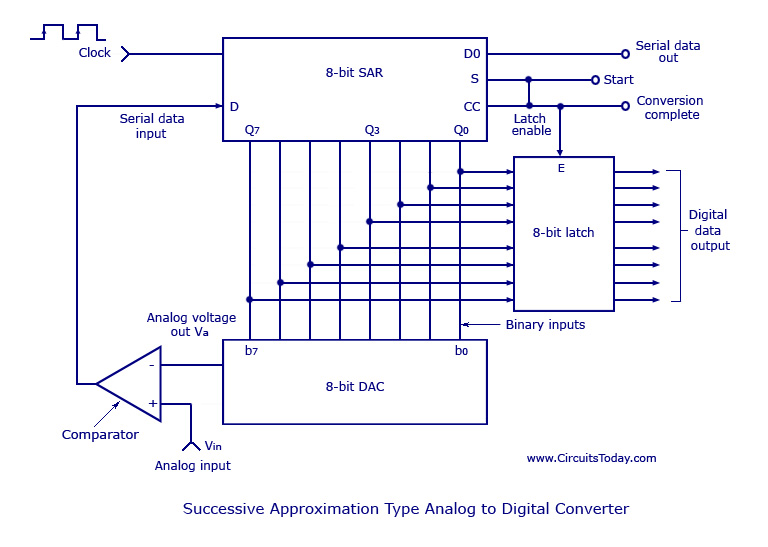
Analog to Digital Converters - Successive Approximation Type Analog to Digital Converter, working, circuit diagram. The Successive Approximation Register (SAR) Analog to Digital Converter (ADC) is a widely used type of ADC that converts an analog signal into a digital...
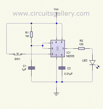
The monostable 555 timer multivibrator circuit, also known as a one-shot monostable multivibrator, functions as a retriggerable pulse generator. The term "monostable" indicates that the circuit has only one stable state, with the unstable state referred to as the...
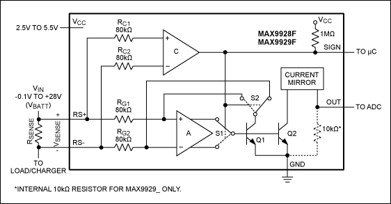
This article compares high-side and low-side amplifiers used for measuring battery charging currents. It recommends selection criteria for current-sense resistors and describes a high-voltage circuit breaker designed for overcurrent protection. High-side and low-side amplifiers are essential components in battery management...
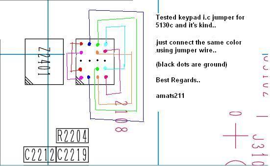
The Nokia 5130 keypad jumper requires following a specific diagram. It has been tested recently, and after implementing the jumper, all keypads are functioning correctly. The Nokia 5130 mobile phone features a keypad that can occasionally experience issues due to...
Traditional UPS systems use analog circuit control, which presents significant limitations for both manufacturers and users, regardless of whether they employ technology or SPWM technology. With advancements in information technology, the introduction of high-speed digital signal processing chips, known...

Sustainable satellite 802.11b wireless internetwork and how it was achieved. The design of a sustainable satellite 802.11b wireless internetwork involves the integration of satellite communication technology with wireless networking standards to create a robust and efficient communication system. This architecture...