
X10 Speech Recognition Interface pg4

The circuit utilizes the PIC 16F877 microcontroller, which is a versatile and widely used component in embedded systems. This microcontroller features multiple I/O pins, enabling direct interfacing with various peripherals, including the digital display output from the speech recognition circuit. The LED serves as an essential visual indicator, signaling to the microcontroller that a speech input has been received.
The comparator's role is critical in this setup. It compares the voltage level from the LED output with the reference voltage generated by the voltage divider formed by resistors R2 and R3. The output from the comparator determines whether the microcontroller receives a high or low signal, indicating the presence of a spoken word.
Upon receiving a valid signal, the PIC 16F877 processes the digital display output to identify the spoken word. If the word matches a pre-defined target, the microcontroller sends the appropriate command and house code to the PL513 Power Line Interface, facilitating control over connected devices.
The circuit's design is user-friendly, allowing for flexibility in assembly. The use of solderless breadboards permits easy modifications and testing. The availability of a PCB kit further enhances the circuit's reliability by minimizing potential wiring errors and improving overall aesthetics.
This schematic effectively showcases the integration of speech recognition technology with microcontroller-based control systems, illustrating a practical application in home automation or similar fields. The detailed parts list and PCB design provide additional resources for individuals interested in replicating or building upon this project.The circuit is based on the PIC 16F877 microcontroller, see schematic in figure 4. The digital display output of the speech recognition circuit connects directly to the pins of the microcontroller. The LED in, provides a trigger that informs the microcontroller when a word has been spoken. The LED output connects to one side of a comparator. The o ther side connects to a voltage divider (Vref) made up of resistors R2 and R3 creating a reference voltage for the comparator. When the LED blinks on the speech recognition circuit it triggers the 16F877 microcontroller on the X-10 interface that a word has been spoken.
The microcontroller then reads the digital display output to determine if the word has been recognized (target word) or non-recognized (error code). If it reads a target word number it transmits the appropriate command and house code to the PL513 Power Line Interface.
The next figure shows my prototyped circuit I build on solderless breadboards. Nothing is critical about the circuit, you can use point to point wiring on standard breadboards if you like. The pc board and circuit is also available as a kit through my company, Images Scientific Instruments Inc.
, see parts list. The pc board is shown below. The kit eliminates wiring error and provides a finished appearance. 🔗 External reference
Related Circuits
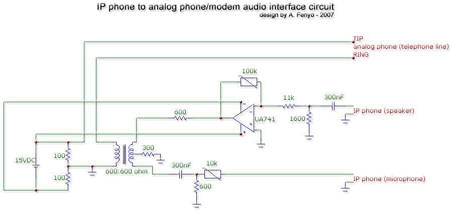
The transformer is a 600:600 ohm transformer, also referred to as a 1:1 ratio 600 ohm transformer. It has approximately the same number of turns on both the primary and secondary coils and is optimized for operation at a...
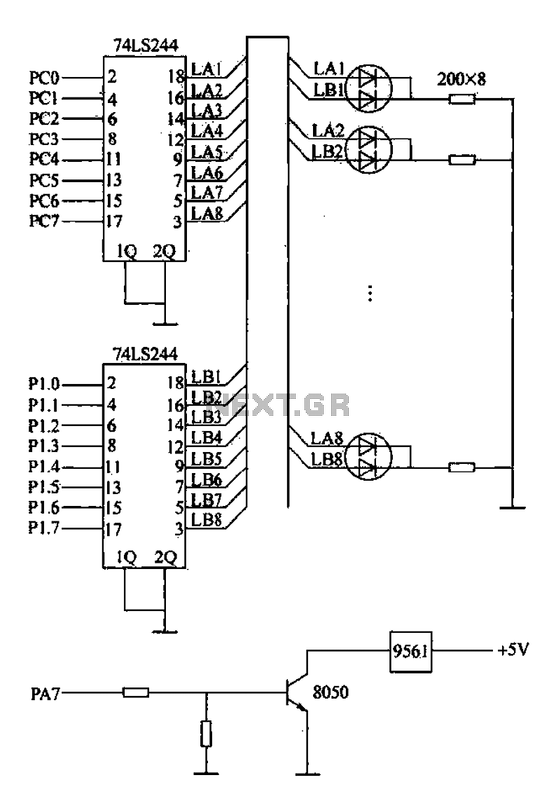
Alarm interface circuitry featuring a two-color light-emitting diode (LED) display. When LAi is at a high level and LBi is low, the green LED lights up; conversely, if LAi is low and LBi is high, the red LED lights...
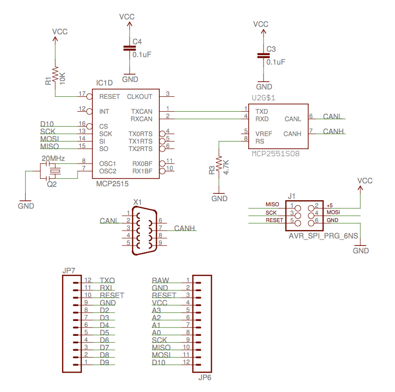
The implementation of the Controller Area Network (CAN) for aircraft applications is referred to as CAN-FIX, which is part of the MakerPlane Open Source Airplane project. This project aims to create an Arduino shield that facilitates communication over the...
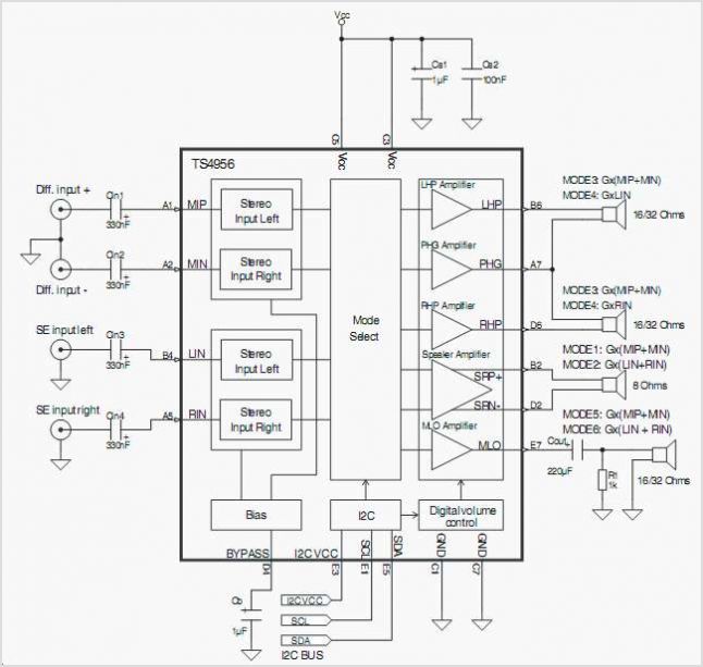
The TS4962 is a differential class-D BTL power amplifier capable of driving up to 2.2W into a 4-ohm load and 1.4W into an 8-ohm load at 5V. It achieves outstanding efficiency (typical 88%) compared to standard AB-class audio amplifiers....
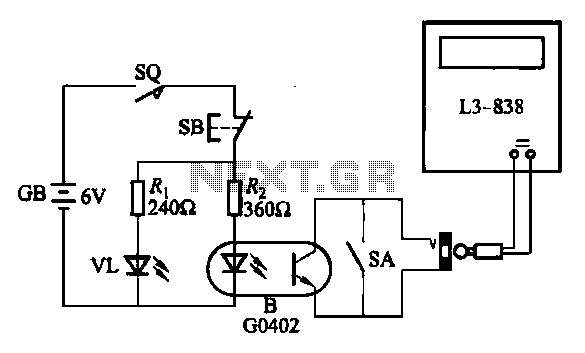
An electronic calculator features an automatic counting interface circuit, as illustrated in the accompanying figures. Figure (a) depicts a stroke switch controlled via optocoupler B. Figure (b) shows the application of a reed switch (KR) for pulse control signals....
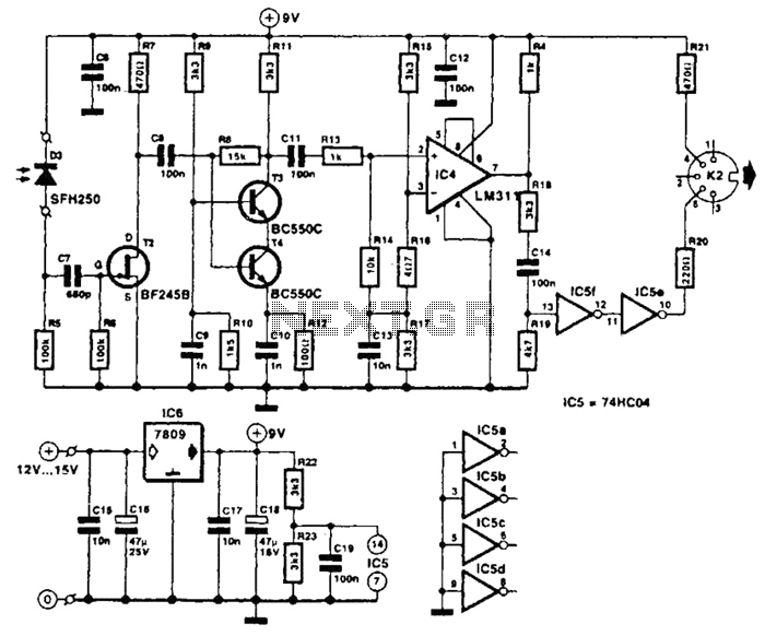
The receiver photodiode SFH250 is utilized to convert optical data pulses at a rate of 32.5 Kbps into electrical signals. The buffer T2 transmits these signals to a cascade amplifier consisting of transistors T3 and T4, followed by an...