
Xenon Flasher

The voltage doubler circuit is designed to convert an AC input voltage into a higher DC output voltage, effectively doubling the voltage available for charging the capacitor. The 60 µF capacitor serves as the energy storage element, accumulating charge until it reaches a voltage sufficient to trigger the SIDAC device. The SIDAC, once activated, allows current to flow through the Xenon lamp, producing a brief and intense flash of light.
The flash rate of the circuit is controlled by the resistors R4 and R5, along with the capacitor C4. These components form an RC timing circuit that dictates how long the capacitor takes to charge and subsequently discharge. Adjusting the values of R4 and R5 will alter the time constant of the circuit, thereby changing the frequency of the flashes emitted by the Xenon lamp.
In practical applications, this circuit can be employed in photographic flash units, strobe lights, or other lighting systems requiring high-intensity bursts of light. The choice of a Xenon lamp is crucial due to its ability to produce a bright flash with a very short duration, making it ideal for applications where quick illumination is necessary. The SIDAC device ensures reliable triggering at a specified voltage, contributing to the overall efficiency and performance of the circuit. Using a voltage-doubler supply, this circuit charges a 60-/aF capacitor and discharges it through a Xenon lamp. The SIDAC dev ice is manufactured by Motorola. It is a two-terminal device that breaks over at a specified voltage. R4, R5, and C4 determine the flash rate.
Related Circuits
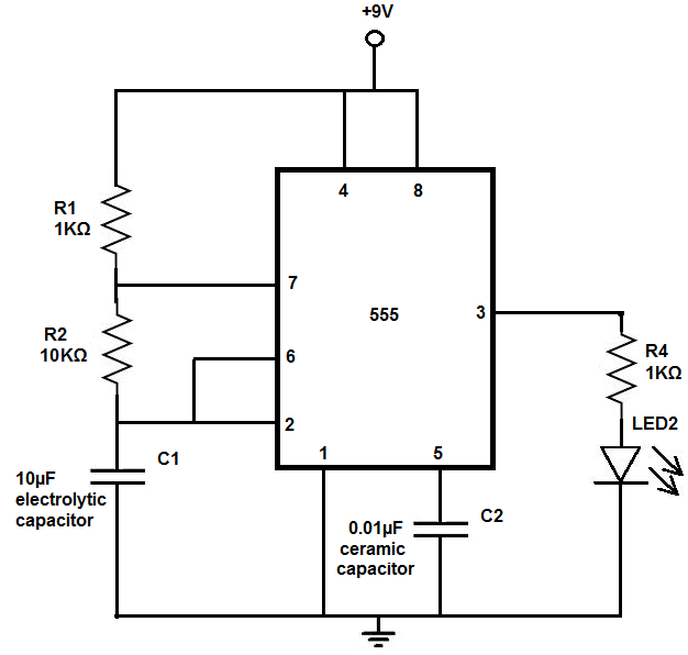
The 555 timer chip is a versatile integrated circuit (IC) that, when connected correctly, can generate pulses of current at specific intervals determined by a resistor-capacitor (RC) network. In this mode, the LED does not remain constantly lit; it...

This simple LED light flasher project utilizes a Hex Inverter 74C04 integrated circuit (IC) to generate a square wave pulse, which is employed to alternately turn two LEDs on and off. The circuit design comprises a 74C04 Hex Inverter IC,...

When we step on the car's brake, then together with the classic rear STOP, the third STOP which is situated in the middle of the back half of the car also switches ON. This is the classic function, found...
This circuit uses three easily available 555 timer ICs. All three work as astable multivibrators. The first 555 has an on period and off period equal to 1 sec. This IC controls the on/ off periods of the other...

This circuit was designed as a warning flasher to alert road users to dangerous situations in the dark. Alternatively, it can act as a bicycle light. The circuit operates by utilizing a light-emitting diode (LED) as the primary visual alerting...
The LED flasher circuits operate on a single 1.5-volt battery. The circuit on the upper right utilizes the widely used LM3909 LED flasher integrated circuit (IC) and requires only a timing capacitor and an LED. The LM3909 is a specialized...