
xenon lamp flash detector

The xenon lamp flash detector circuit is designed to detect the intense light flashes emitted by xenon lamps, which are commonly used in photography and high-intensity lighting applications. The circuit operates with a low standby current, making it energy-efficient while maintaining high sensitivity to light flashes.
At the core of the circuit, a photodetector, such as a photodiode or phototransistor, is employed to capture the light emitted by the xenon lamp. Upon detecting a flash, the photodetector generates a small electrical signal. This signal is then amplified by a transistor or operational amplifier to ensure it reaches a sufficient level for further processing.
The output of the amplification stage can be fed into a flip-flop circuit, which serves as a bistable multivibrator. This configuration allows the circuit to toggle between two states (on and off) based on the input signal from the photodetector. When a flash is detected, the flip-flop changes its state, which can be used to control other devices or indicate the presence of the flash through an LED or other output indicators.
Key components of this circuit include a power supply, the photodetector, an amplifier stage, the flip-flop, and output indicators. The circuit design should also incorporate necessary resistors and capacitors to stabilize the operation and filter out noise, ensuring reliable performance in various lighting conditions.
Overall, this xenon lamp flash detector circuit is a practical solution for applications requiring light detection with minimal power consumption while providing a reliable means to control additional circuitry based on the detection of xenon lamp flashes.This circuit is xenon lamp flash detector. It has a very low standby current requirement yet has very high sensitivity toward the light flashes from a xenon lamp. When connected to a flip/flop it can serve as an on on/off controller. 🔗 External reference
Related Circuits
The core component of this DIY metal detector circuit is the CS209A. The metal detector is constructed using a single 100 µH coil. The CS209A features an oscillator that creates an LC circuit; the inductance of the coil alters...
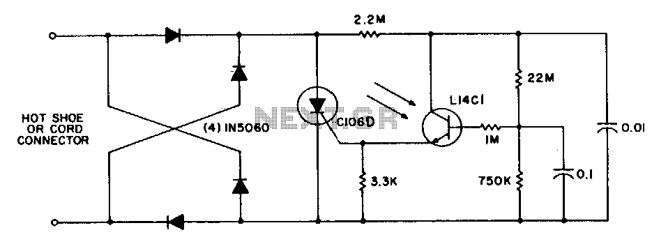
This circuit is utilized for remote photographic flash units that synchronize with the flash attached to the camera. It is designed to connect to the trigger cord or hot shoe of a commercial portable flash unit, allowing the unit...
At half brightness, the lamp current is pulsed on and off by the voltage developed across the resistor and capacitor at the current-sense output. The current-sense output detects the lamp current. A basic pulse-width modulation (PWM) lamp-brightness control circuit...

This 220V mains operated solid-state flashing lamp circuit utilizes a 555 timer integrated circuit (IC) to manage the ON and OFF durations of a triac that regulates power to the load. The circuit operates at a mains voltage of 220V,...

Cl, VDI, VD2, C2 form a simple capacitive step-down voltage regulator circuit with a rectifier output providing approximately 8V DC voltage for the LM567. A 5.6-foot manifold is connected. Resistors R3, RP, and capacitor C3 create an ultra-low frequency...

The UHF motion detector operates on the Doppler radar principle. Q1 is an oscillator that creates a radiated signal. An object in the radiated field reflects some of this energy back to the detector. If the object is moving,...