
XTal Tester

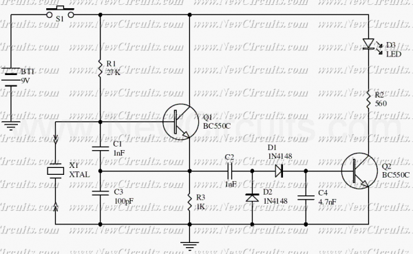
The described circuit utilizes a transistor (T1) in conjunction with a crystal oscillator (XTal) to generate an oscillating signal. Capacitors C1 and C2 serve as voltage dividers, ensuring that the oscillator receives the appropriate voltage levels for stable operation. The crystal oscillator operates effectively within the specified frequency range of 100 kHz to 30 MHz, provided that the crystal is functioning properly.
The output from the oscillator is then processed through capacitors C3 and C4, which are employed for filtering and smoothing the rectified output voltage. Diodes D1 and D2 are configured in a rectifying arrangement, converting the AC signal generated by the oscillator into a DC voltage suitable for powering subsequent components.
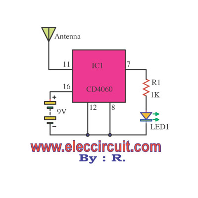
Transistor T2 acts as a switching device that is activated by the rectified output. When T2 is energized, it completes the circuit for the LED, allowing it to illuminate as an indicator of proper operation. This circuit is particularly useful for testing the functionality of various crystals within the specified frequency range, ensuring they can oscillate effectively when integrated into other electronic applications. The design emphasizes simplicity and efficiency, making it an ideal choice for basic testing and troubleshooting in electronic projects.T1 and XTal have formed an oscillator. C1 and C2 are voltage divider for oscillator. if the XTal is safe, the oscillator will work well and its output voltage will be rectified by C3, C4, D1 and D2, then T2 will run and LED will light. The circuit is suitable to test 100KHz - 30MHz Xtal. 🔗 External reference
Related Circuits
Here is a handy gadget for testing of infrared (IR) based remote control transmitters used for TVs and VCRs etc. The IR signals from a remote control transmitter are sensed by the IR sensor module in the tester and...
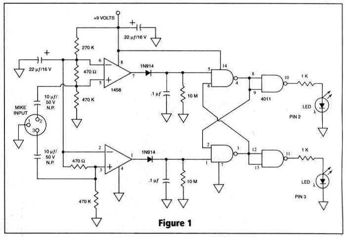
Many things can go wrong in a modern recording studio, but few are as difficult to track down as reversed microphone polarity. When a microphone is placed in front of a sound source, a positive pressure on its diaphragm...
Tools that feature the equivalent of a professional, easy-to-use, cheaper, and, more importantly, safe for use. They are designed for checking and identifying AC voltages of 220 Volt or 120 Volt. The tools mentioned are essential for ensuring electrical safety...
Transistor Q1, a 2N3563, and its associated components form an oscillator circuit that will oscillate if, and only if, a good crystal is connected to the test clips. The output from the oscillator is then rectified by the 1N4148...
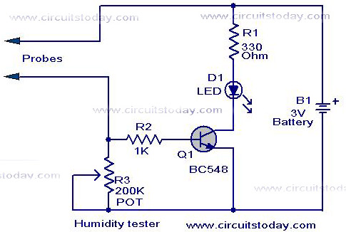
A simple humidity tester circuit using only an LED, a transistor, and a few resistors is explained with a clear circuit schematic. The humidity tester circuit is designed to provide a visual indication of humidity levels using basic electronic components....
This is a simple XTal tester circuit. T1 and XTal have formed an oscillator. C1 and C2 are voltage divider for oscillator. if the XTal is safe, the oscillator will work well and its output voltage will be rectified...