
Class A Headphone Amplifier II

Transformers in the audio signal path are even worse: non-linearities in the gain structure, parasitic capacitance between windings, impedance problems.... Transformers belong in linear power supplies and nowhere else. Ultra high open loop gain: REAL, REAL BAD!!! That basically means anything with an opamp in it. Opamp circuits with open loop gains of 10,000 or more require large amounts of feedback to make them usable.
While this reduces THD, the intermodulation products, and especially the transient intermodulation products are much higher than they should be. The schematic for the standard (non-bridged output) version of the headphone amplifier is shown in figure 1.
The open loop gain of the amplifer is about 35. Even with the feedback removed, the THD is less than .01%. That's important because the more linear an amplifier is without feedback, the more the THD, IM and TIM distortions are reduced to unmeasurable levels with feedback added. Stage 1 is a dual FET fully-differential fully-balanced front-end. The idling current is 2mA total per dual FET (1mA per FET) and 4mA for the complete front-end stage which consists of both dual FETs.
The dual FETs generate the bias which runs the second stage, and keeps it and the resulting output section in class A at all times. The FETs are ultra low noise dual units specifically designed for audio uses. The total voltage gain of the first stage is 50. Stage 2 is the driver stage. It is a standard class A voltage amplifier - in this case used as a voltage shifter. The voltage gain is 0.5 and the idling current 4.3mA. The push-pull class A output stage is a series of paralleled emitter follower, current buffers. The voltage gain is 0.9 and the current gain is 75. The idling current is 15mA per transistor (or 60mA for the 8 transistors off the +16VDC rail and 60mA for the 8 transistors off the -16VDC rail).
I have designed the output section to run at what I have determined is the sweet spot for these transistors, which is 15mA each. Yeah, it gets hot; its supposed to get hot (but not hot enough to require heatsinks). It's not possible to make an amplifier with an output impedance less than 0.1 ohm without throwing around a fair amount of current.
The servo circuit is new: most of the servo designs (Mark Levinson and Krell, for example) put the output of the DC servo back into the - leg of the amplifier. I just do not like this. That puts the noise and non-linearities of the opamp inside the audio loop. My servo feeds back to the current sources for the dual FETs in stage 1. Like all servos, it is an integrator. Due to the large (relatively) integration capacitor and the 1 meg resistor, the frequency of this filter is 0.05 Hz.
With even a decent opamp, the servo's noise is in the tens of microvolts, and does not affect the operation of the current sources significantly. The servo opamp in this amplifier measures the DC at the output, if any, integrates it and applies it to the midpoint of the two LEDs.
The LEDs do have a slight change in voltage with respect to current, about 3 or 4%, and that is enough to make the servo work. Notice that if the transistors or the resistors are very poorly matched, the servo will not work because its total control range is at most 10%.
Most standard servos (such as the Mark Levinson or Krell servos) have a much wider range. For high impedance headphones, a little DC will not hurt the phones. With the low impedance Grados, even 0.1VDC over a long period of time will definitely damage and/or change the sound. If all the parts are hand matched, the power supplies are exactly the same and all the resistors are really good quality, the amp should be stable and should not drift.
In that case, the servo could be omitted or replaced with a 20K trimmer pot wired from +16VDC to -16VDC, with the wiper going to the DC adjust pin. The prototype uses 0.05% tolerance resistors, and I hand-matched the transistors. The output DC is less than 6mV and has stayed absolutely stable for the few months I have had the unit.
Servo loops MUST NOT be in the audio feedback loop. This rule is also very important. Two of my favorite high-end audio electronics manufacturers put servo loops into the minus input of their amplifiers. Most other manufacturers that use servo loops do the same thing. opamps used for servo loops do not have an output impedance low enough to make them suitable for this purpose.
Furthermore the dynamic output impedance of opamps adds non-linearities to the audio when put in series with the gain resistor on the minus input. 🔗 External reference
Related Circuits
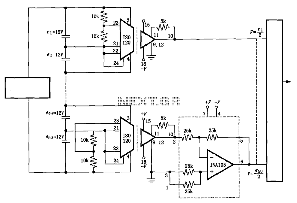
The circuit utilizes the ISO120 and INA105 instrumentation amplifiers to create a battery monitoring system for a 600V battery setup composed of 50 series-connected 12V batteries. This circuit is designed to detect charging and discharging conditions to prevent overcharging...
The lower FET operates in common source mode, while the upper FET operates in common gate mode, achieving full high-frequency gain. The bottom FET is tunable, allowing for peak adjustment for a particular station. Coil details follow: The described circuit...
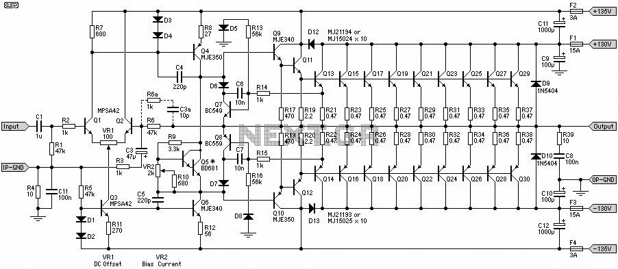
This 1500W Power Amplifier Circuit Diagram contains two images of the circuit. For more complete information, refer to the main post titled "1500 Watt Power Amplifier." It includes a list of component parts for the 1500W Power Amplifier Circuit...
Output-clamp diodes are mandatory because loudspeakers are inductive loads. Output LR isolation is also used because audio amplifiers are usually expected to handle up to 2 mF load capacitance. Large, supply-bypass capacitors located close to the IC are used...
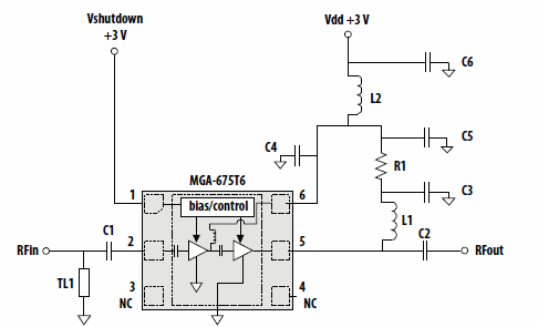
This application note discusses the use of Avago Technologies' MGA-675T6 for 5-6 GHz applications. The MGA-675T6 is internally integrated with shutdown and biasing circuitry, which simplifies the external circuitry. The shutdown feature allows the low noise amplifier (LNA) to...
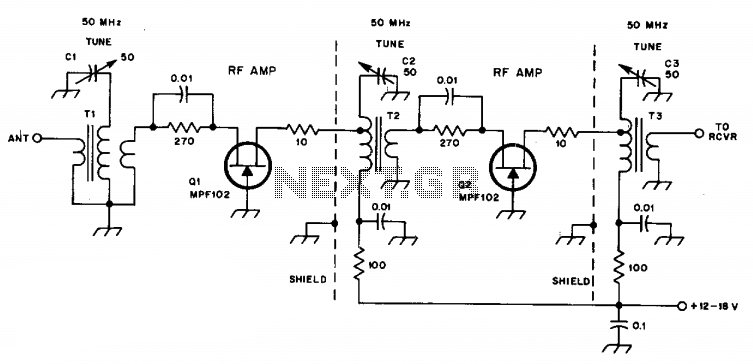
C1, C2, and C3 are miniature ceramic or plastic trimmers. T1 (main winding) has an inductance of 0.34 µH, utilizing 11 turns of No. 24 enameled wire wound on a T37-10 toroid core. The antenna winding consists of one...