
5w 150mhz rf amplifier circuit

The RF amplifier circuit operates within a frequency range of 150 MHz and is designed to deliver an output power of 5 watts. The core component, the MRF123 TMOSFET, is known for its high gain characteristics, making it suitable for amplification tasks in RF applications. However, the high gain can lead to instability, particularly at VHF and UHF frequencies. To mitigate this issue, a 68 Ohm resistor is placed at the input. This resistor serves to dampen potential oscillations and improve the overall stability of the amplifier circuit.
The amplifier's gain of 14 dB indicates that the output signal is significantly amplified relative to the input signal, providing a robust amplification solution for RF signals. The drain efficiency of 55% reflects the ratio of output power to the total power consumed by the amplifier, suggesting that the circuit is relatively efficient in converting DC power into RF output power.
In terms of circuit design, it is essential to ensure proper biasing of the MRF123 to achieve the desired operating point. Additionally, careful attention should be paid to the layout of the circuit to minimize parasitic inductances and capacitances, which can adversely affect performance. The use of decoupling capacitors at the power supply lines is recommended to filter out noise and stabilize the voltage supply, further enhancing the amplifier's performance.
Overall, this RF amplifier circuit is a practical solution for applications requiring reliable amplification of RF signals within the specified frequency range, balancing gain, stability, and efficiency.This is a 5W -150MHz RF amplifier circuit. It applies the MRF123 TMOSFET. The MRF123 is a very high gain FET which potentially unstable at both VHF and UHF frequencies, so the 68 Ohm input loading resistor has been used to enhance the stability. This RF amplifier has a gain of 14 dB and a drain effeciency of 55%. 🔗 External reference
Related Circuits
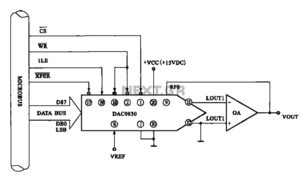
Figure 8 illustrates a typical digital-to-analog (D/A) conversion circuit that utilizes the DAC0830/DAC0832 chip. The microprocessor outputs an 8-bit digital signal, which is converted into an analog signal. The D/A conversion circuit depicted employs the DAC0830/DAC0832, which is a dual...
Using two LT1228 transconductance amplifiers in front of a current feedback amplifier creates a video fader. The ratio of the set currents into pin 5 determines the ratio of the inputs at the output. The proposed circuit utilizes two LT1228...
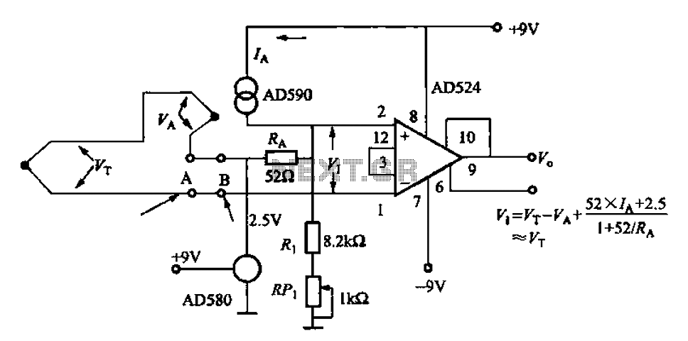
The AD524J type thermocouple cold junction temperature compensation circuit is illustrated in Figure 1-20. This circuit utilizes J-type thermocouples, with the base reference voltage sourced from the AD580, an integrated temperature sensor, and the precision instrumentation amplifier AD524. The...
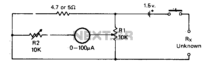
For the measurement of resistances ranging from approximately 5 ohms down to about 0.1 ohm. This circuit is highly practical. The described circuit is designed to measure low resistances with high precision, specifically in the range from 5 ohms down...
The combination of the LM4651 driver IC and the LM4652 power MOSFET Class D power amplifier IC provides a high-efficiency amplifier solution, suitable for self-powered speakers, subwoofers, and quality car boosters. The LM4651 is a fully integrated conventional pulse...
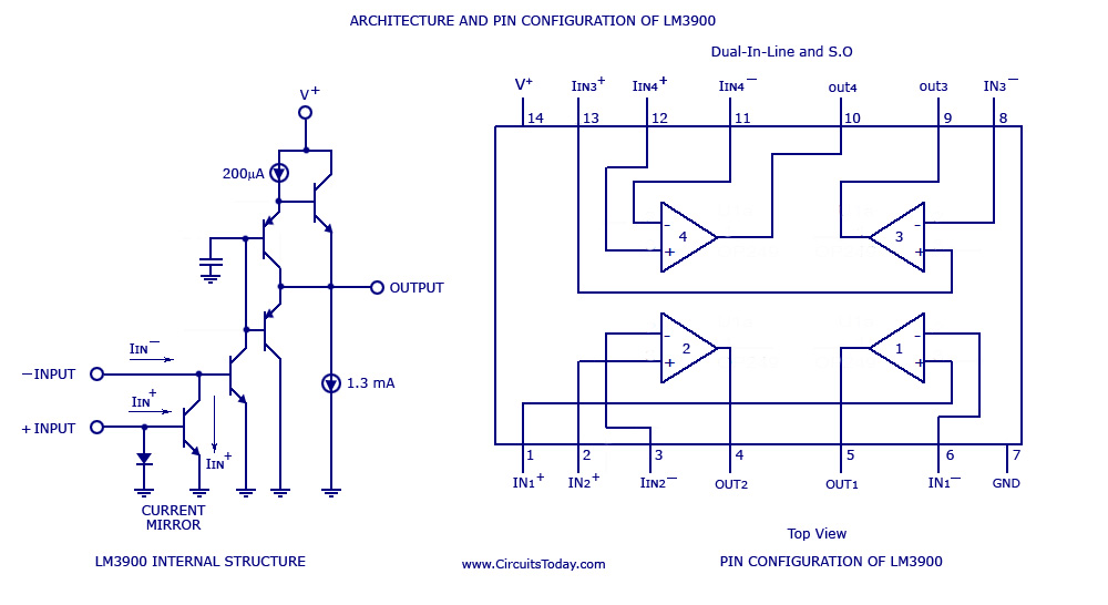
A simple multi-channel audio mixer circuit utilizing the LM3900 quad amplifier is presented below. The circuit features a four-channel quad amplifier (LM3900) with two microphone audio inputs and two direct line inputs. By paralleling additional circuits, the number of...