
quick on board junction tester circuit diagram

In electronic circuit diagnostics, the identification of short circuits and broken tracks on printed circuit boards (PCBs) is crucial for troubleshooting and maintenance. A multimeter serves as a fundamental tool in this process, allowing for the detection of continuity and resistance in the circuitry. When measuring the integrity of components such as transistors and diodes, the multimeter can provide misleading readings if these components remain soldered to the PCB. This is due to the influence of surrounding circuitry, which can alter the expected values.
To obtain accurate measurements, it is recommended that transistors and diodes be desoldered from the PCB prior to testing. This ensures that the multimeter readings reflect the true characteristics of the device without interference from other components. Additionally, the physical constraints of using a multimeter can complicate the testing process. The user must maintain a stable connection with the probes while also positioning the multimeter for visibility, which can lead to potential errors in reading.
For enhanced testing efficiency, alternative methods such as using a dedicated transistor tester or diode tester can be employed. These specialized devices are designed to measure the performance of semiconductors with greater accuracy and ease of use. They typically feature built-in displays that eliminate the need for awkward positioning of the multimeter, thereby streamlining the testing process.
Furthermore, incorporating automated testing systems can significantly reduce the manual effort involved in diagnosing PCB issues. These systems can perform multiple tests in succession and provide detailed reports on the condition of various components, thus facilitating quicker and more accurate troubleshooting. By leveraging advanced testing methodologies, the reliability of electronic circuits can be assured, leading to improved overall performance and longevity of the devices.Short circuits or broken pcb tracks can be easily recognized by means of a Multimeter, but this tool can give wrong results when testing the efficiency of a transistor or diode, unless the device under test is unsoldered and removed from the pcb. A further shortcoming affecting such way of testing is the necessity to keep firmly the probes on the pins of the device under test and at the same time to turn the head continually to read the Multimeter display..
🔗 External reference
Related Circuits
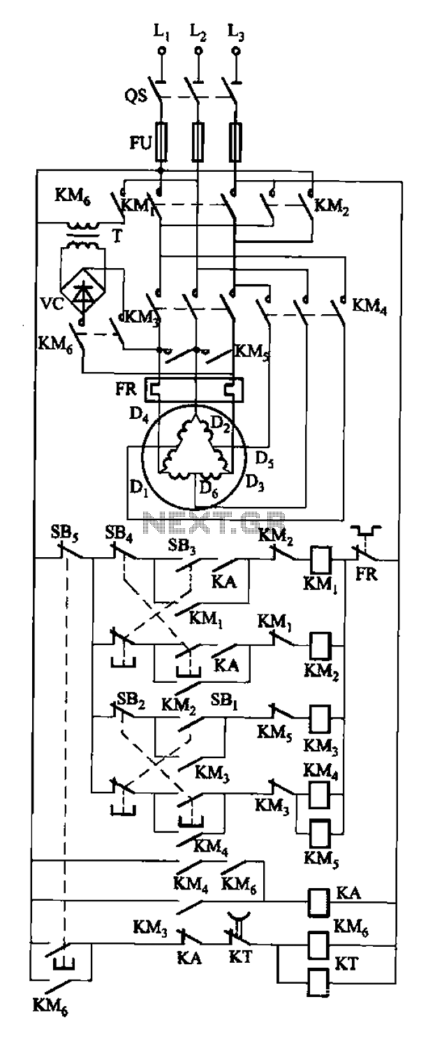
The circuit depicted in Figure 3-108 includes various control buttons: SB3 for the forward button, SI for the reverse button, SBi as the low start button, SB2 for the speed start button, and SBs for the stop button. KMs...

As environmental awareness increases, electric cars have become an essential part of people's transportation. Preventing electric car theft is a significant concern for owners. Various electric vehicle anti-theft locks have been developed; however, theft of electric cars continues to...

This project is a successful vacuum tube amplifier utilizing a 6V6GT output pentode configured in triode mode, producing approximately 4.5 watts of output power. The design features a single-ended audio amplifier with a resistive input network, a driver stage,...

This simple circuit can be used to protect a bike from theft. It produces a loud alarm tone if someone attempts to start the bike. The alarm can only be disabled when the hidden switch S2 is opened. The...
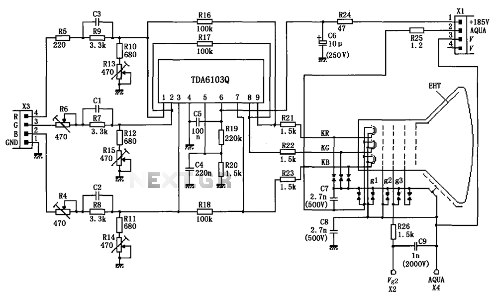
The circuit depicted in the figure integrates the TDA6103Q with a color picture tube, illustrating its practical application. The red, green, and blue (R, G, B) input signals are received from the input socket X3 and processed through a...
Many amateur receivers are equipped with an S meter that does not operate logarithmically. The proposed circuit is intended to enhance such receivers. Although integrated circuits like the CA3089 or CA3189 are not commonly used today, they play a...