
Zero center indicator for FM receivers

The circuit described involves a tuning mechanism for receiving radio signals, specifically focusing on achieving a null condition for optimal reception. The "I'M pot" refers to an adjustable potentiometer used for fine-tuning the input signal. The process begins by tuning into the desired radio station and adjusting the potentiometer until a null point is reached, where the output signal is minimized or balanced.
Once the null condition is established, the station is requested to modulate. This modulation is likely a test signal that varies in amplitude or frequency to ensure the receiver's response is appropriate. The fine-tuning process is critical; it involves adjusting the potentiometer further to ensure that modulation peaks do not activate the LEDs. The LEDs serve as indicators of signal strength or modulation presence. Therefore, the goal is to achieve a state where neither LED is illuminated, which indicates that the station is properly tuned and the receiver is optimally configured to handle the incoming signal without distortion or overload.
In summary, the tuning procedure is essential for ensuring clear reception of radio signals while avoiding false indications from the LEDs, which would suggest improper tuning or excessive modulation. Proper adjustment of the I"M pot is crucial in achieving this balance, leading to an effective and efficient radio communication system.To adjust, tune in a station and adjust the I"M pot for a null. Then ask the station to modulate and fine adjust so modulation peaks don"t light the LEDs Stations are properly tuned when neither LED is lit.
Related Circuits
A balance indicator for a power supply that shows whether a symmetric power supply is truly symmetric. It utilizes two pairs of comparators from an LM339N quad comparator. The balance indicator circuit employs the LM339N quad comparator to assess the...
The circuit indicates that the phone is in use by illuminating a red LED. When the phone is not in use, a green LED lights up. It operates without requiring external power and can be connected at any point...

The circuit is a simple RF-actuated switch that responds to any strong electromagnetic field in the vicinity of the pickup wire. The length of the wire will depend on the required coupling, but a 250 mm length wrapped around...
Firstly because of the modulation process we generate at least two copies of the intelligence plus the carrier. For example consider a local radio station transmitting on say 900 Khz. This frequency will be very stable and held to...
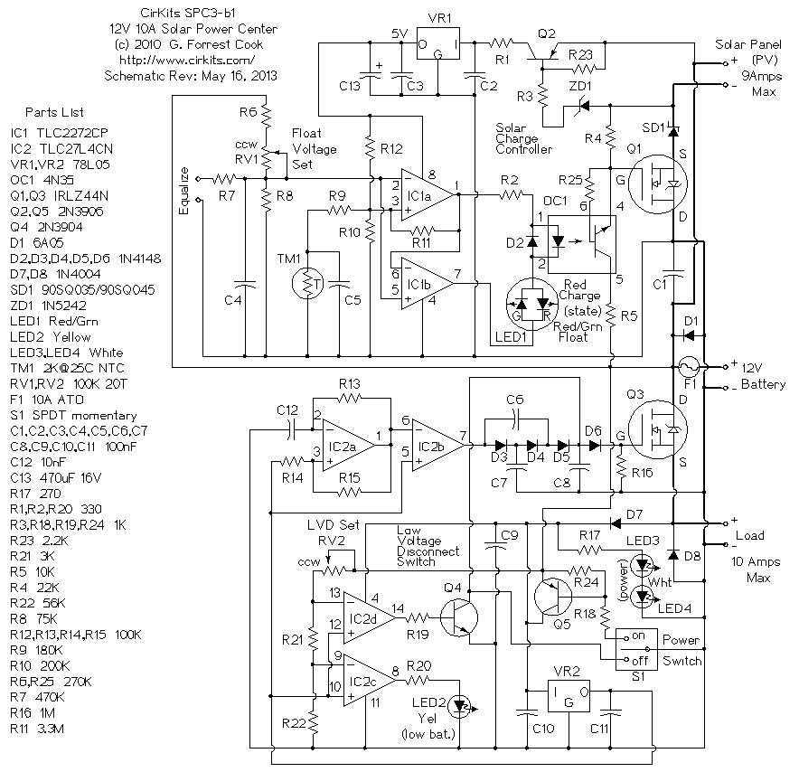
The SPC2 is a solar power center, it can be used to handle all of the power functions for small 12 Volt solar powered devices. It contains a photovoltaic charge controller and a low voltage load disconnect circuit. The...
The operating principle of the circuit is very simple. The first LED D1 is placed in series with the resistor R2 and diode D4. An only be lit this LED indicates that the battery is overcharged. For this reason,...