
Balance Indicator for Symmetric Power Supply
The balance indicator circuit employs the LM339N quad comparator to assess the symmetry of a dual power supply. This device contains four independent comparators, enabling the design of two pairs that can be used to compare the voltage levels of the positive and negative rails of the power supply.
The circuit is configured such that each comparator in the pair receives input from one of the power supply rails. The reference voltage for comparison can be set to ground or a predefined voltage level, depending on the desired sensitivity of the indicator. When the voltages on the two rails are equal, the outputs of the comparators will reflect this balance, providing a clear indication of symmetry.
The outputs from the comparators can be connected to LED indicators or a display module to visually represent the symmetry status. If the voltage levels deviate, the corresponding LED will illuminate, signaling an imbalance in the power supply. This visual feedback allows for quick diagnostics and ensures that the power supply operates within the required specifications for balanced performance.
In practical applications, this balance indicator can be integrated into power supply units used in audio equipment, instrumentation, and other electronic systems where voltage symmetry is crucial for optimal operation. The simplicity and effectiveness of using LM339N comparators make this circuit an efficient solution for monitoring power supply balance.Balance indicator for power supply show if a symmetric power supply is really symmetric or not. With two comparator pairs from a LM339N quad comparator we.. 🔗 External reference
Related Circuits
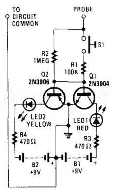
This circuit utilizes two switching transistors and two LEDs to differentiate between low-level AC and DC signals. A lit red LED indicates a positive DC signal, while a lit yellow LED signifies a negative DC signal. If the input...
The following diagram represents a 20W power amplifier circuit constructed using the EL34 tube component. The EL34 is a well-known tube that is highly regarded for use in power tube amplifiers. The circuit includes both the tube amplifier schematic...
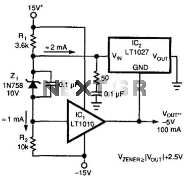
A method for enhancing the output current of a reference while also providing overload protection is illustrated. In this configuration, IC1 functions as a power buffer. The LT1027 regulates the output voltage (Vout) and ground to maintain a stable...

This schematic is essential. Visit this page to find a comprehensive pre-amplifier and power amplifier design for your guitar, which includes a complete explanation of its operation and instructions on how to construct the enclosure. The provided schematic outlines a...
The supply voltage should be about +/- 35 Volts at full load, which will let this little guy provide a maximum of 56 Watts (rated minimum output at 25 degrees C). To enable maximum power, it is important to...
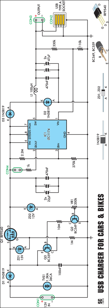
A regular charger was tested and found to consume 13mA with no load. It features an integrated power LED, which significantly contributes to standby current consumption. However, since the cigarette lighter socket is powered only when the engine is...
Warning: include(partials/cookie-banner.php): Failed to open stream: Permission denied in /var/www/html/nextgr/view-circuit.php on line 713
Warning: include(): Failed opening 'partials/cookie-banner.php' for inclusion (include_path='.:/usr/share/php') in /var/www/html/nextgr/view-circuit.php on line 713