
Zero consumption Anti-theft High power Code Switch for E-Bike Batteries


Introduction to the project
Standard key switches used in e-bike batteries often present several issues. Manufacturers typically employ inexpensive key lock switches that can be easily compromised with a screwdriver or specialized tools. Additionally, users must always carry the key, risking loss while away from home. The aesthetic of traditional keys also appears outdated in today's digital landscape. This project includes protective features to prevent unintentional deactivation, which will be discussed further.
Despite the seemingly complex appearance of the nine-button keypad, the underlying circuit is simple enough for anyone with basic electronics knowledge to construct. A printed circuit board (PCB) is not necessary.
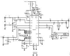
The physical circuit diagram provided simplifies the construction process, utilizing only seven components: three thyristors (such as the BT169 or similar), three resistors, one latching relay (HFE10-2-12-HT-L2), and a pre-assembled DC/DC converter.
Thyristors and resistors are readily available in local markets, although the specific relay may require sourcing online or finding a comparable alternative.
The DC/DC step-down converter is a widely recognized module that delivers a continuous output of 3A. It is a non-isolated buck converter with a fixed output of either 9V or 12V (12V is recommended). The input voltage options range from 16-90V or 16-120V, with either being suitable; the latter is preferred. This converter boasts low power consumption and an impressive conversion efficiency of approximately 96%. Efficiency improves as the differential input/output voltage decreases.
No labeling is required on the buttons, as users can memorize the code sequence visually. If modifications to the code sequence are desired, the button positions can be rearranged, provided the wiring remains intact.
Before commencing, it is essential to ensure sufficient space on the bike for the relay and module. The relay should be positioned near the thick positive power wire (typically red) connecting the battery management system (BMS) to the controller. The positive wire may need to be cut and soldered to the relay, replacing the existing key switch if present.
This project is particularly suitable for custom battery casings that allow for additional space. In this instance, the aluminum top casing was intentionally designed to be 5 cm taller at the front to accommodate converters, chargers, an alarm system, and a GPS tracking module.
Construction
Starting with the buttons, any waterproof button type that fits well on the bike can be used. Arranging the buttons closely together creates a keypad appearance, deterring potential thieves while enhancing aesthetics. Measure the button diameter, adding 2-3 mm spacing between them to determine the center distance. Mark the centers on a piece of paper, cut it to size, and position it where the buttons will be installed. Secure the paper in place and use a center punch to mark the holes on the casing. After drilling, install the nine buttons. A PCB is not necessary, as the button backs serve this purpose. Solder the resistors and thyristors according to the diagram, keeping wires clean and short to avoid clutter. Hot glue can be used to secure loose wires.
Position the relay and DC/DC module as required, connecting them according to the diagram. In this case, the relay is located near the controller, while the DC/DC converter is placed close to the keypad buttons. Short cables minimize weight and enhance accessibility for future adjustments.
Instructions, Coding, and Settings
This project employs thyristors to create a sequential activation pattern. Button 7 activates the second thyristor, followed by button 2 activating the third thyristor. Button 4 then energizes the latching relay's coil, transitioning it to the ON state.
To switch ON, the sequence 724 must be entered while holding button 6. If an incorrect button is pressed, the sequence resets. Buttons 1, 5, 9, and 3 serve as reset buttons, intended to confuse potential thieves; it is possible to use only one of these buttons. Button 8 is designated for switching OFF, while button 6 acts as a "hold to use" button, powering the entire coding system. This design ensures no power consumption occurs in either the ON or OFF state, as the controller remains disconnected from power. Therefore, button 6 must be continuously pressed before entering the ON or OFF sequence.
To summarize the coding:
- Switch ON code: By holding button 6, enter 724.
- Switch OFF code: By holding button 6, enter 8.
If the relay behaves oppositely to the intended function, swapping the 1 and 2 terminals may resolve the issue.
The relay used is compact, lightweight, and powerful, featuring two coils instead of one, and requires no power to maintain its state due to internal magnets. If a single-coil latching relay is available, circuit modifications will be necessary for compatibility.
For sourcing the relay HFE10-2-12-HT-L2 and the DC/DC down converter, links to suppliers are available.This project fits more for custom made battery casing that can have more space to hide things inside. This switch with few alterations can be used for any other project as well but is designed based on e-bike needs!
This project use a clever functionality of thyristors to create a sequential pattern. It has protection feature from accidental switching OFF action..
Note: This type of switch with few alterations can be used for any other project as well but is designed based on e-bike needs!
Introduction to the project
There are several problems with the standard key switch of the e-bike battery. Usually manufacturers place a cheap key lock switch. The first disadvantage of this type of switches is that can be easily violated with a screwdriver or by using professional thief key technics.
Another headache is to keep always the key on you and try to not lose it while you are away from home. Also the key looks too ugly and obsolete in our modern digital days. This solution has protection feature from accidental switching OFF action. More about this later on.
Although the appearance of 9 square formed buttons (Keypad) looks digital and complicated, this circuit
is so simple that anyone can build for his bike with just the basic electronics knowledge.
You even don't need a PCB.
At the illustration I have made the physical circuit diagram to make your life easier. Just 7 components are being used here.. 3 thyristors (BT169 or any other similar type can be used), 3 resistors, 1 latching relay type HFE10-2-12-HT-L2, and a ready build DC/DC converter.
The thyristors and resistors are easy to find at your local area but the specific relay is a bit difficult.
You can buy it from the net or you can use a similar type available to you!
The DC/DC Step Down converter is a known Chinese Module that provides 3A continuously. Is a Non-isolated Buck Converter and auto-stabilizer with fixed output of 9V or 12V (choose 12V). The input voltages have two options 16-90V or 16-120V (any will do.. I use the 16-120V type). It has very low power consumption and great conversion efficiency of ~96%. The smaller the differential input/output voltage, the higher the efficiency.
You don't need numbering or letters on buttons.
You will memorize the code sequence by your photographic memory once for ever. The coding settings will be explained later. If you want to change the sequence code, you can change the buttons position as you like to be. At the diagram I intentionally placed numbers on the buttons randomly so to explain the functionality of the circuit. You can alter the position of the switches to change the code as you like as long as you keep the correct wiring.
Before you start
Make sure you have space on your bike!
All has to do with the available space you have to hide the relay and the tiny module. Keep in mind that the relay should be close to your thick power wire (usually red) that is coming from the BMS to your controller. Between this distance you should find a place to secure the relay. The positive (red) wire will be cut and soldered on relay or removed from old key switch if exist and will be substituted by the relay, wired as the diagram shows.
This type of project fits more for custom made battery casing that can have more space to hide things inside.
In my case the aluminum top casing cap was made intentionally taller 5cm at the front. to hide more converters and chargers along with the bike's alarm and the GPS-Tracking module.
Construction
Starting from the buttons (dark red at image) that can be any waterproof type of button that fits well to your bike. Place buttons physically close to look more like a keypad, this keeps passing thieves away and looks cool too.
Measure your button diameter add 2-3mm spacing between them and find the distance of their centers. So now you can take the ruler and mark the 9 centers on a peace of paper. Cut the paper parallelogram and place it on the position you want the buttons. Stick the paper stable and use a center punch to mark the holes on casing. Open the holes and place your 9 buttons. You will not need actual PCB for this circuit so your PCB is your buttons back. Solder the resistors and the thyristors as you see it on the diagram. Keep the wires clean and as short as possible. You don't want a wire mess in there. Use hot glue to secure flying wires etc.
Secure the relay and the DC/DC module where you need them and connect them accordingly following the diagram. In my case the relay is placed at the far back near the controller
and the DC/DC converter is placed near the keypad buttons.
Keeping in mind that cables adds weight, keep them short. It will be easier accessible later if needed.
Instructions, Coding and Settings
This project use a clever functionality of thyristors to create a sequential pattern.
Button 7 passes current to the second thyristor and button 2 passes then the current to the third thyristor. Then button 4 passes the current to the Latching relay's specific coil for ON state.
So to switch ON you need to hit the 724 buttons with the right sequence only! If a wrong button is pushed in between the code will reset everything.
Buttons 1, 5, 9 and 3 are reset buttons.
These buttons just resets the entry. Are there to only confuse the thief. In practice you can remove 3 of them and use only one of these 4 buttons.
Button 8 change switch to OFF state
Button 6 is the "hold to use" button. This is the power on for the hole codding system. This is the reason for stating "Zero consumption" at the title. Button 6 gives power to DC/DC converter to power the switching circuit. So no power at all is being used for either ON or OFF state,
nor the controller consume anything as is completely disconnected from power.
So you need this button (6) to be always pressed before you enter the switch ON or the switch OFF code.
So to conclude codding:
If coding does the oposite than the wanted, just swap the 1 and 2 terminals of the relay.
For the OFF state you need something fast and quick, so only one button is being used. But with the demand of the holding 6 button makes a good protection from accidental pressing the 8 button.
You can place more thyristors and buttons to make the ON code longer etc.
The Particular relay is small light and powerful. It has two coils and not one. It needs no power to hold the state as it uses magnets internally. If you have a single coil latching relay available, then you need to alter the circuit to be use it.
For Relay HFE10-2-12-HT-L2 supplier : Click here
For the DC/DC down converter supplier : Click here
Enjoy your rides and your new cool switch ;)
Related Circuits
A good way to mount the circuit board is to use a hot glue gun to mold the circuit underneath the lamp housing. There is plenty of space there for your board. At the next photos you can see...
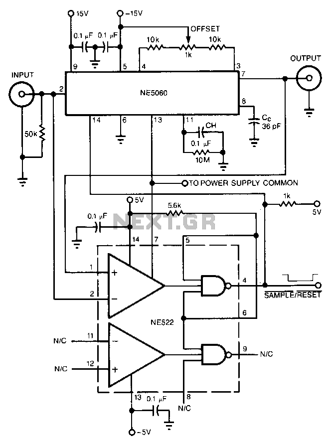
The high-speed peak detector utilizes a highly accurate, fast sample-and-hold (s/h) amplifier that is controlled by a high-speed comparator. The s/h amplifier retains the peak voltage until the comparator switches the amplifier to its sample mode to capture a...
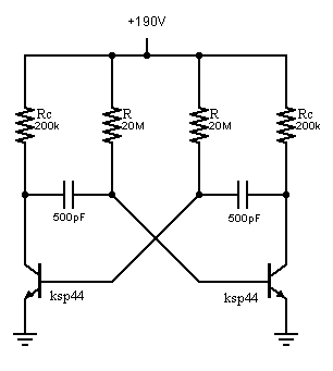
An oscillator is being developed to operate within the 200V range, targeting a frequency of approximately 1 kHz while minimizing current consumption. Initial testing has commenced. The design of a high-voltage oscillator capable of operating at 200V and generating a...
In today's environment, characterized by viruses and various threats from the Internet, it is essential to have assurance that a PC remains protected from infections. This circuit... To enhance the security of personal computers against viral threats and malware, a...
This sensitive sound-operated switch can be used with a dynamic microphone insert or with an electret (ECM) microphone. If an ECM is used, then R1 (shown dotted) will need to be included, with a suitable value between 2.2k and...
A typical circuit for applications such as mobile phones, MP3 players, and portable electronics utilizing the SSM2602 Low Power Audio Codec is provided in the SSM2602 Applications Circuit Schematic. The SSM2602 Low Power Audio Codec is designed for high-performance audio...