
Audio Mixer 6 Channel circuit
The 6-channel mixer circuit is designed to facilitate audio mixing with flexibility and control over multiple input sources. The six input channels allow for a variety of audio signals to be processed simultaneously. Channels 1 through 4 are mono, making them suitable for single audio sources, while channels 5 and 6 can accommodate stereo signals, particularly beneficial for music applications.
The sound control potentiometers (RV1-6) serve to adjust the volume levels for each channel independently, providing the user with the ability to balance audio levels according to their requirements. The additional potentiometers (RV7-12) are critical for maintaining the balance between the left and right audio channels, ensuring a cohesive sound output.
The summing stage, utilizing operational amplifiers IC1A and IC1B, plays a pivotal role in combining the audio signals from the various channels. The inclusion of trimmers (TR1-2) allows for fine-tuning of the gain for each operational amplifier, enabling precise control over the output signal levels. This feature is particularly useful for adapting to different audio sources and ensuring optimal performance.
Following the summing stage, the three-band equalizer (IC3) is implemented to allow the user to adjust the tonal quality of the audio output. This equalizer provides control over low, mid, and high frequencies, allowing for customization of the sound to suit specific preferences or requirements. The design ensures that the equalizer operates with isolation from previous stages, maintaining audio integrity.
For headphone monitoring, the circuit incorporates a dedicated headphone amplifier using IC2A and IC2B. This component provides a headphone output at JF13, allowing users to monitor audio signals directly. The design ensures that the headphone output is clear and provides sufficient volume for effective monitoring.
Additionally, the circuit features tracks for optical audio levels, which can be utilized for visual monitoring of audio signal levels through a stereo level meter. This feature enhances the usability of the mixer, allowing for real-time feedback on audio performance.
Overall, the 6-channel mixer circuit is a versatile and comprehensive solution for audio mixing applications, equipped with essential features for sound control, equalization, and monitoring.The following is a main circuit of the mixer-6 Ch The circuit consists of six input channels. The mono channels are channels 1-4 and 5-6 CH CH, are intended for use by music. The number of input channels you want as she can greatly increase you want. The output of each channel drives the RV1-6, the level of sound control potesometer. With RV7-12 c reate the conditions of equilibrium between the two channels (BALANCE). All signal input channels are added at this point two vipers [IC1A-b] for each channel has two trimmer Here TR1-2 to adjust the gain of each IC, adapting the level of the output signal in the level we want. That can be suppressed if you need something and Standard and Poor. The next stage is a three-band equalizer of regulation. The IC3 ±-b, are off the table, they want an acre to make a profit and they want to do the essential isolation of the previous stages, with the unit that drives us.
For whoever they want to use headphones, there is a classic circuit unit of the headphones around the IC2a-b, which give the output in the JF13. There are also tracks can also optical audio levels, with a stereo level meter. 🔗 External reference
Related Circuits
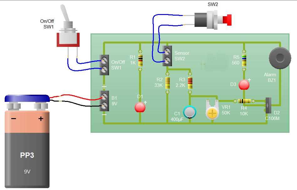
When the sensor switch SW2 is pressed, the LED D3 and the alarm are activated for a certain duration. The timing of the circuit is determined by the resistor R3 and capacitor C1. Additional details regarding the RC circuit...
Mobile phone chargers available in the market are quite expensive. The circuit presented here serves as a low-cost alternative to charge mobile telephones or battery packs with a rating of 7.2 volts. The proposed circuit design utilizes a straightforward approach to...
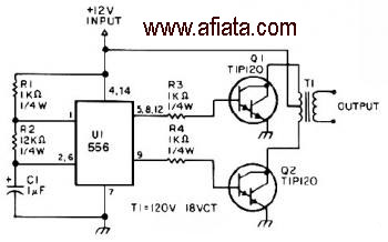
The first section of the 555 timer is configured as an astable oscillator, with R2 and C1 determining the frequency. The output is accessible at pin 5. The second section functions as a phase inverter, with its output available...
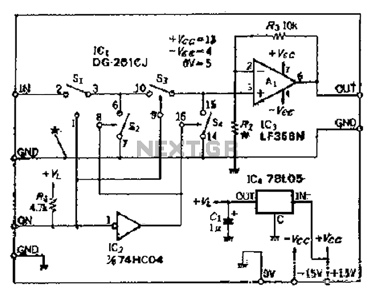
Analog switches SL and SA disconnect the inverted logic signal to terminal 2. S1 and S4 are turned on, allowing capacitance between S1 and S8 to couple. S2 and S4 shunt with an on-state resistance ranging from 50 to...
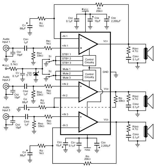
The LM4782 utilizes a protection system known as National Self Peak Instantaneous Temperature (Ke) (SPiKeTM). SPiKe safeguards the output of the LM4782 against over-voltage on the load, short circuits to ground, and provides temperature protection by monitoring instantaneous temperature....
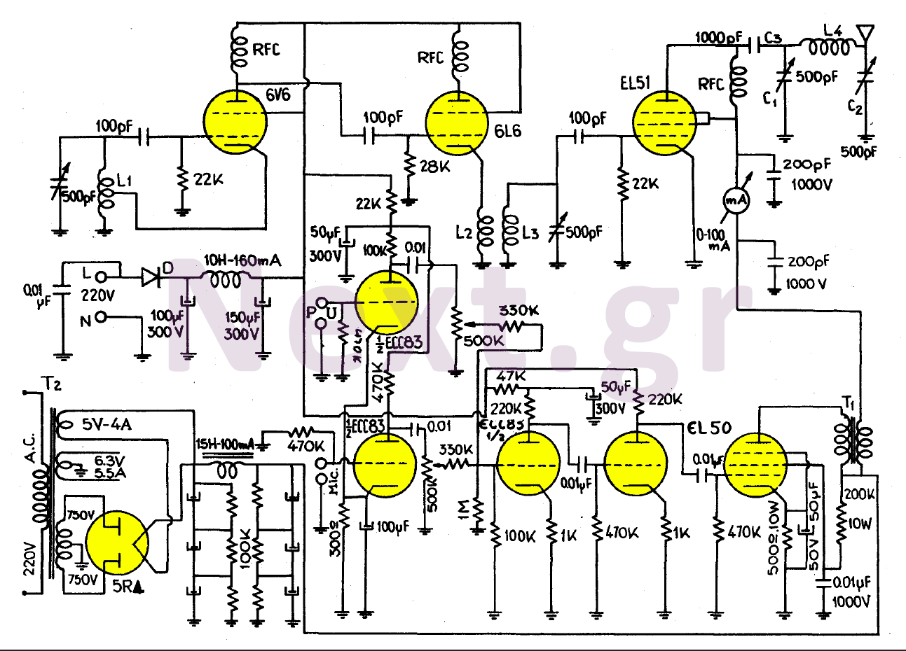
This transmitter, equipped with a quality antenna and utilized under optimal conditions, can achieve a range exceeding 45 km. The configuration benefits from the output lamp's elevation, enhancing the fidelity of the transmitted signal. The 6V6 lamp is employed...