
Leakage protection switch circuit diagram

The multifunction leakage protection switch featuring the Nissan ASIC M54122L is an advanced circuit designed to ensure electrical safety by detecting leakage currents and responding to electrical shocks. The core operation involves the interaction of magnetic fields generated by current flowing through inductor lines and neutral connections. In normal conditions, these magnetic fields counteract, resulting in no AC voltage across the coil. However, upon detection of a leakage current or electric shock, the coil generates a voltage, which is sensed by pin 7 of the ASIC. This condition activates a thyristor, which is a semiconductor device that acts as a switch, effectively disconnecting the relay from the power supply and thereby preventing potential hazards.
The overvoltage protection mechanism is critical in safeguarding the circuit from transient voltage spikes, such as those caused by lightning strikes or faults in the neutral line. The circuit employs a varistor (Ru1), which is designed to absorb excess voltage. As the supply voltage rises, the resistance of Ru1 decreases, allowing more current to flow. This results in an increase in voltage across resistor R5. When the voltage exceeds a threshold of approximately 275V, the voltage across R5 reaches about 1.8V, which is sufficient to trigger the protective action through the combination of resistors R4 and diode D1. This design ensures that the circuit remains operational under normal conditions while providing robust protection against electrical faults, thereby enhancing the safety and reliability of electrical systems where this multifunction leakage protection switch is implemented.As shown Multifunction leakage protection switch utilizing Nissan ASIC M54122L, it can be composed of multi-function leakage protection switch, when the leakage and electric sh ock, the magnetic field through the inductor line and neutral generated cancel each other on the coil AC voltage is not generated. When the leakage or electric shock, the coil generates a voltage, pin 7 produces a high triggered thyristor, so that the relay off the power.
Overvoltage protection by the Ru1, Ru2, Ru4, Ru5, D1 composition. Ru1 varistor for absorbing lightning or neutral failure caused by overvoltage. When the supply voltage is increased, Ru resistance becomes smaller, the R5 voltage increases when the supply voltage is equal to 275V, the voltage of about 1.8V on the R5 through R4, D1 trigger protection.
Related Circuits
To prevent soldering errors, students were instructed to place all their resistors on the board first. Once their placements were verified, they could proceed with soldering. Capacitors were next, followed by LEDs and other components. The middle school class...
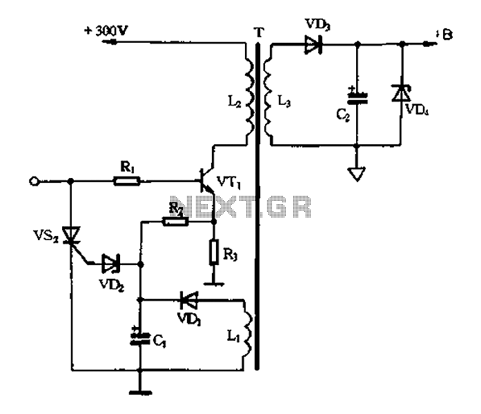
Color TV main power protection circuit The color TV main power protection circuit is designed to safeguard the television's power supply from various electrical anomalies, such as overvoltage, undervoltage, and short circuits. This circuit typically employs several components, including fuses,...
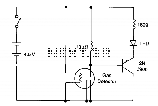
The circuit illustrates a basic yes/no gas detector. It utilizes three 1.5-V D cells as the power source, with SI functioning as an on/off switch. The heater is powered directly from the battery, while the electrodes are connected in...
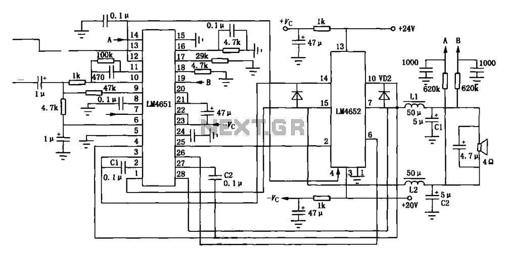
Figure (a) illustrates a 170W output amplifier circuit designed for a 4-ohm load. The LM4651 is a class D amplifier presented in a 28-pin DIP package, with its internal equivalent circuit depicted in Figure (c). The 170W output amplifier circuit...
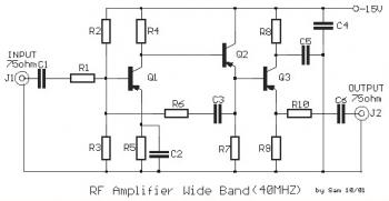
This is a 40 MHz RF amplifier circuit. The sensitivity of a receiver can be significantly enhanced by integrating this circuit between the receiver and the antenna. The amplifier does not utilize resonant circuits and is suitable for both...
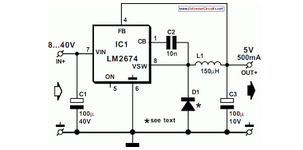
National Semiconductor has been producing and designing integrated circuits (ICs) for use in switch-mode power supplies for many years. The application of these devices is standard. National Semiconductor has established a significant presence in the design and manufacturing of integrated...