
LM4561 LM4562 consisting of 170W power amplifier circuit

The 170W output amplifier circuit is engineered to drive speakers with a nominal impedance of 4 ohms, making it suitable for high-power audio applications. The LM4651 class D amplifier utilizes pulse-width modulation (PWM) to efficiently convert the input audio signal into a high-power output while minimizing heat generation.
The 28-pin DIP package of the LM4651 facilitates easy integration into various circuit designs. It includes essential features such as over-temperature protection, short-circuit protection, and a built-in low-pass filter to smooth the PWM output, ensuring high fidelity in audio reproduction.
The internal equivalent circuit of the LM4651, as shown in Figure (c), provides insight into the amplifier's operational characteristics, including the arrangement of transistors, feedback loops, and the power supply configuration. The efficient switching mechanism of the class D architecture allows for high output power levels while maintaining low distortion, making it ideal for modern audio amplification needs.
Further analysis of the circuit design reveals the importance of component selection, including the choice of inductors and capacitors, which directly impacts the amplifier's performance and efficiency. Proper layout considerations in PCB design are also crucial to minimize parasitic inductances and capacitances, ensuring optimal signal integrity and thermal management within the amplifier. Overall, this amplifier circuit exemplifies the advancements in audio amplification technology, combining high power, efficiency, and compact design.Figure (a) shows the output amplifier circuit 170W at 4 loads; LM4651 is a former circuit class D amplifier, a 28-pin DIP package, the internal equivalent circuit is shown in ( c),
Related Circuits
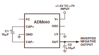
The ADM660 is a charge-pump voltage converter that can either invert the input supply voltage or double it. The schematic below depicts the ADM660 Voltage Inverter Circuit Configuration Diagram. This inverting schematic is ideal for generating a negative rail...
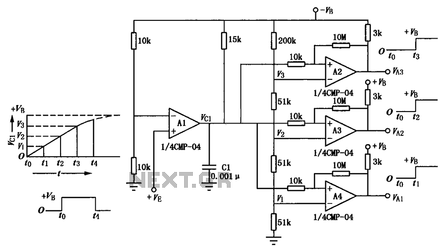
A multi-stage delay circuit is presented in this schematic. The operational amplifiers are configured as comparators. Operational amplifier A1 operates when the voltage at the inverting input exceeds + VE. As the voltage at the inverting input of operational...
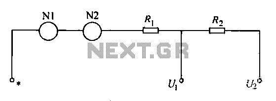
A voltmeter operates through a measuring mechanism in a specified circuit, utilizing a moving coil in series with additional resistance. The fixed coil is denoted as N1, while the moving coil is designated as N2. The additional resistances are...
This circuit was designed and manufactured in the 1980s and has functioned without issues since then. It does not present any particular constructional problem, beyond the known: the attention in the provided force of power supply, choice of suitable...
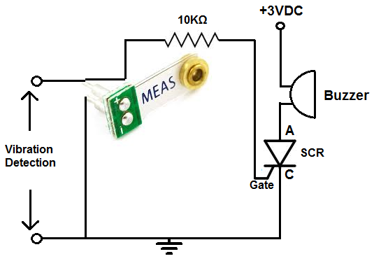
This alarm is designed for use in a room or area that should typically remain motionless. In an environment devoid of movement, no vibrations will be detected, and the alarm will remain inactive. However, once the circuit identifies a...
%2B2%2BCH%2Bby%2BIC%2B%2BNE5532%2Bor%2BLF353.jpg)
This is a microphone preamplifier circuit model 2 CH. The circuit utilizes integrated circuits NE5532 or LF353 to amplify the sound signal from a dynamic microphone, increasing the power level for subsequent input into a stereo power amplifier. This...