
Gas analyzer circuit
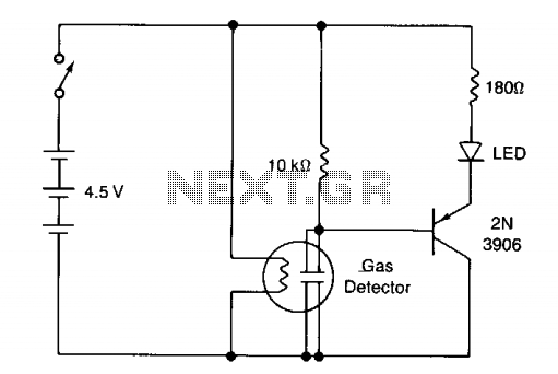
When the sensor is exposed to contaminated air, the resistance decreases, leading to an increased voltage drop across the 10 kΩ resistor. Once the sensor resistance drops to around 10 kΩ or lower, the transistor begins to turn on, allowing current to flow through the LED, which then emits light. A 180 Ω resistor is included to limit the current through the LED to a safe level.
The gas detector circuit operates on a straightforward principle where the change in resistance of the gas sensor is the key parameter for detection. The arrangement of three 1.5-V D cells in series provides a total supply voltage of 4.5 V, which is adequate to power the heater and the monitoring circuitry. The PNP transistor acts as a switch that is controlled by the voltage across the 10 kΩ resistor.
In clean air conditions, the relatively high resistance of the sensor prevents sufficient current from flowing through the transistor, keeping the LED off. However, as the air quality deteriorates and the sensor detects gas, the resistance drops significantly. This drop causes an increase in voltage across the 10 kΩ resistor, which can exceed the threshold required to turn on the PNP transistor. When activated, the transistor allows current to flow from the emitter to the collector, energizing the LED and providing a visual indication of gas presence.
The inclusion of the 180 Ω resistor is critical as it ensures that the current flowing through the LED remains within safe limits, preventing damage to the LED and ensuring reliable operation. This simple yet effective design provides a clear yes/no indication of gas presence, making it suitable for various applications, including home safety and industrial monitoring.The circuit shows a simple yes/no gas detector. Three 1.5-V D cells are used as a power supply, with SI acting as an on/off switch. The heater is energized directly from the battery, while the electrodes are in series with a 10 k resistor. The voltage across this resistor is monitored by a pnp transistor. When the sensor is in clean air, the resistance between the electrodes is about 40 k, so that only about 0.9 V is dropped across the 10 k resistor.
This is insufficient to turn on the transistor, because of the extra 1.6 V required to forward bias the light emitting diode (LED) in series with the emitter. When the sensor comes in contact with contaminated air, the resistance starts to fall, increasing the voltage dropped across the 10 k resistor. When the sensor resistance falls to about 10 k or less, the transistor starts to turn on, current passes through the LED, causing it to emit.
The 180 ohm resistor limits the current through the LED to a safe value. 🔗 External reference
Related Circuits
The circuit utilizes a thermistor and three sections of a LM3900 quad operational amplifier (op amp) integrated circuit. When the temperature decreases to 36°F, an LED indicator flashes approximately once per second. As the temperature continues to drop to...
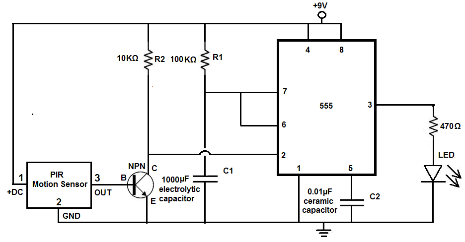
Many individuals install motion detectors in their backyards or homes to automatically turn on lights when movement is detected. Motion sensor lights have gained popularity and are increasingly utilized in various settings. Businesses frequently employ them in bathrooms, where...
Radio Control Circuits PDF Manual Download. This document serves as a comprehensive guide to radio control circuits, intended for individuals seeking to understand the principles and applications of radio frequency (RF) technology in controlling various devices. The manual covers fundamental...
The Zener diode may not be providing sufficient current in its breakdown state to activate the transistor. Removing resistor R2 did not resolve the issue. The Zener's voltage selection could be too high, potentially preventing it from regulating the...
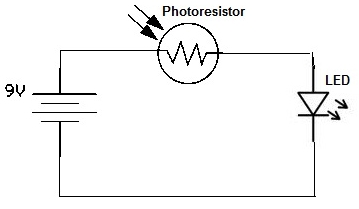
A simple photoresistor circuit will be constructed to demonstrate the operation of a photoresistor, which activates the circuit in the presence of light and deactivates it in darkness. This circuit connects a photoresistor to an LED. When the photoresistor...
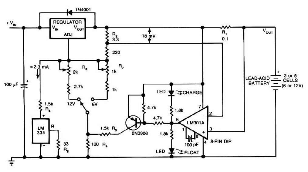
The schematic for this charger is straightforward. It is designed to charge a Gel Cell or other lead-acid types. This simple battery level monitor circuit can indicate the charging process in a 12 Volt lead-acid battery or tubular battery....
Warning: include(partials/cookie-banner.php): Failed to open stream: Permission denied in /var/www/html/nextgr/view-circuit.php on line 713
Warning: include(): Failed opening 'partials/cookie-banner.php' for inclusion (include_path='.:/usr/share/php') in /var/www/html/nextgr/view-circuit.php on line 713